Using a Let’s Encrypt Cluster Issuer for Certificate Manager

I’m a big fan of Let’s Encrypt as its a great service that provides free TLS certificates for your applications and websites. This post summarizes the steps to setup Let’s Encrypt as the cluster issuer for certificate manager.

A Cluster Issuer enables your applications to automatically request TLS certificates from Let’s Encrypt. It basically avoids having to do the following manually:

  • Typing certbot certonly --manual --cert-name something.domain.com --preferred-challenge=dns to create a manual TLS request.
  • Then going to your DNS service and creating the TXT record.
  • Then downloading the cert.pem and privkey.pem.
  • Then creating a secret to use the new certificate.

Pre-requisites

  1. A Kubernetes cluster, I’m using a TKG cluster
  2. A domain name managed by a well-known domain registrar (I’m using Cloud Flare, but Route 53 and others can also be used)

Step 1. Install Cert Manager into your Kubernetes cluster

# Install Tanzu Standard Repository
tanzu package repository add tanzu-standard --url projects.registry.vmware.com/tkg/packages/standard/repo:v2024.2.1 --namespace tkg-system

# Create namespace for cert-manager tanzu packages
k create ns my-packages

# Install cert-manager 
tanzu package install cert-manager --package cert-manager.tanzu.vmware.com --namespace my-packages --version 1.12.2+vmware.2-tkg.2

# Install cert-manager custom resource definitions
kubectl apply -f https://github.com/cert-manager/cert-manager/releases/download/v1.14.4/cert-manager.crds.yaml

Step 2. Create a Secret for Cloud Flare

I am using Cloud Flare as my DNS provider. Cloud Flare has an API that can be used with an API Token or an API Key. I am using an API Key to allow Let’s Encrypt to verify domain ownership with Cloud Flare.

You can get your API Key by following this screenshot.

Then create the following file secret-cloudflare.yaml.

apiVersion: v1
kind: Secret
metadata:
  name: cloudflare-api-key-secret
  namespace: cert-manager
type: Opaque
stringData:
  api-key: <your-cloud-flare-api-key>
  # - or -
  # api-token: your-api-token

Step 3. Create the Let’s Encrypt Cluster Issuer

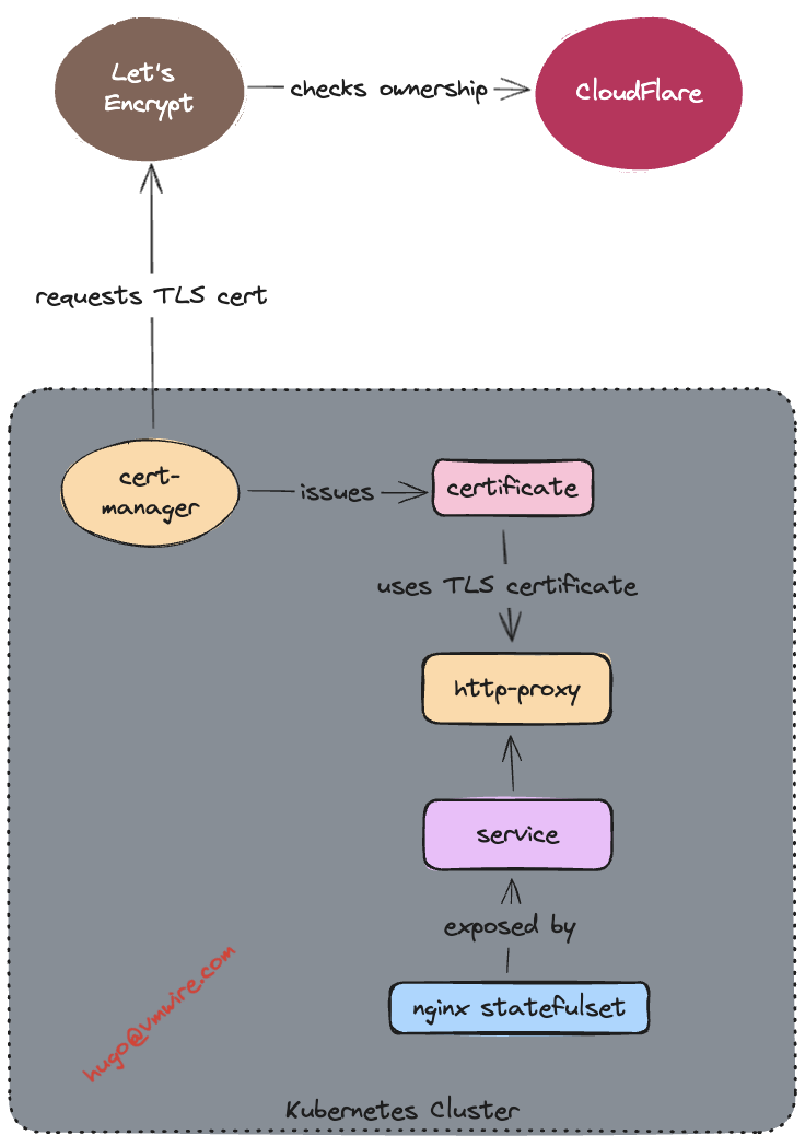
I am using Let’s Encrypt as the certificate issuer and it will check the validity of the certificate request against the domain ownership in Cloud Flare using the Secret created in Step 2.

Create another file named cluster-issuer-production.yaml.

apiVersion: cert-manager.io/v1
kind: ClusterIssuer
metadata:
  name: letsencrypt-production
spec:
  acme:
    email: <your-email-address>
    # Letsencrypt Production
    server: https://acme-v02.api.letsencrypt.org/directory
    # - or -
    # Letsencrypt Staging
    # server: https://acme-staging-v02.api.letsencrypt.org/directory
    privateKeySecretRef:
      name: example-issuer-account-key
    solvers:
    - dns01:
        cloudflare:
          email: <your-cloudflare-email-account>
          apiKeySecretRef:
            name: cloudflare-api-key-secret
            key: api-key

Step 4. Apply both files to create the Secret containing the Cloud Flare API Key and the Cluster Issuer.

kubectl apply -f secret-cloudflare.yaml

kubectl apply -f cluster-issuer-production.yaml

Your cluster is now ready for automatically issuing TLS certificates using Certificate Manager.

Example Application

The following is an example application manifest that uses the letsencrypt-production ClusterIssuer to request a TLS certificate from Let’s Encrypt named nginx.k8slabs.com.

My test domain k8slabs.com is running in Cloud Flare.

The manifest has the following sections:

  • namespace – creates the nginx namespace for all of the resources below
  • service – ClusterIP service for nginx to expose the nginx pod created by the
  • statefulset – creates the statefulset that will deploy the nginx pods
  • certificate – issued by the ClusterIssuer using Let’s Encrypt and checks validity against the DNS records in CloudFlare
  • httpproxy (ingress) – creates an ingress and uses the certificate created by the ClusterIssuer to expose the nginx application over secure TLS

Sample application nginx-statefulset-contour-tls.yaml

---
apiVersion: v1
kind: Namespace
metadata:
  name: nginx
  labels:
    name: nginx
---
apiVersion: v1
kind: Service
metadata:
  name: nginx-service
  namespace: nginx
spec:
  selector:
    app: nginx
  ports:
    - name: http
      port: 80
      targetPort: 80
      protocol: TCP
  type: ClusterIP
---
apiVersion: apps/v1
kind: StatefulSet
metadata:
  name: nginx
  namespace: nginx
spec:
  selector:
    matchLabels:
      app: nginx
  serviceName: "nginx-service"
  replicas: 1
  template:
    metadata:
      labels:
        app: nginx
    spec:
      terminationGracePeriodSeconds: 10
      containers:
      - name: nginx
        image: k8s.gcr.io/nginx-slim:0.8
        ports:
        - containerPort: 80
          name: nginx
---
apiVersion: cert-manager.io/v1
kind: Certificate
metadata:
  name: nginx
  namespace: nginx
spec:
  secretName: nginx
  issuerRef:
    name: letsencrypt-production
    kind: ClusterIssuer
  dnsNames:
    - 'nginx.k8slabs.com'
---
apiVersion: projectcontour.io/v1
kind: HTTPProxy
metadata:
  annotations:
  labels:
    app: nginx
  name: nginx-httpproxy
  namespace: nginx
spec:
  routes:
  - conditions:
    - prefix: /
    pathRewritePolicy:
      replacePrefix:
      - prefix: /
        replacement: /
    services:
    - name: nginx-service
      port: 80
  virtualhost:
    fqdn: nginx.k8slabs.com
    tls:
      secretName: nginx

Visual View

Expose Kubernetes Dashboard with Contour

Dashboard is a web-based Kubernetes user interface. You can use Dashboard to deploy containerized applications to a Kubernetes cluster, troubleshoot your containerized application, and manage the cluster resources. You can use Dashboard to get an overview of applications running on your cluster, as well as for creating or modifying individual Kubernetes resources (such as Deployments, Jobs, DaemonSets, etc). For example, you can scale a Deployment, initiate a rolling update, restart a pod or deploy new applications using a deploy wizard.

Dashboard also provides information on the state of Kubernetes resources in your cluster and on any errors that may have occurred.

In the previous posts, I’ve described how to deploy Kubernetes Dashboard with TLS certs and expose using a Load Balancer service.

This post shows you how you can expose the Dashboard using Contour with TLS certificates.

Step 1. Download the Kubernetes Dashboard manifest

https://raw.githubusercontent.com/kubernetes/dashboard/v2.7.0/aio/deploy/recommended.yaml

Step 2. Edit the file

Go to the kubernetes-dashboard Service and add in another line to make the service a ClusterIP service for Contour to use. It should look like this:

kind: Service
apiVersion: v1
metadata:
  labels:
    k8s-app: kubernetes-dashboard
  name: kubernetes-dashboard
  namespace: kubernetes-dashboard
spec:
  ports:
    - port: 443
      targetPort: 8443
  selector:
    k8s-app: kubernetes-dashboard
  type: ClusterIP

Go to the kubernetes-dashboard-certs Secret and add in your tls certificate and private key for the Dashboard in base64 format and change the type to kubernetes.io/tls. It should look something like this:

apiVersion: v1
kind: Secret
metadata:
  labels:
    k8s-app: kubernetes-dashboard
  name: kubernetes-dashboard-certs
  namespace: kubernetes-dashboard
data:
  tls.crt: LS0tLS1CRUdJTiBDRVJUSUZJQ0FURS0tLS0tCk1JSUU1VENDQTgyZ0F3SUJBZ0lT--snipped--
  tls.key: --snipped--
type: kubernetes.io/tls

Go to the kubernetes-dashboard Deployment spec.template.spec.containers.args section and add in these two lines:

            - --tls-cert-file=/tls.crt
            - --tls-key-file=/tls.key

It should end up looking something like this:

    spec:
      securityContext:
        seccompProfile:
          type: RuntimeDefault
      containers:
        - name: kubernetes-dashboard
          image: kubernetesui/dashboard:v2.7.0
          imagePullPolicy: Always
          ports:
            - containerPort: 8443
              protocol: TCP
          args:
            - --tls-cert-file=/tls.crt
            - --tls-key-file=/tls.key
            - --auto-generate-certificates
            - --namespace=kubernetes-dashboard

Step 3. Add in the Contour httpproxy

Go all the way to the bottom of the file and add in this section, of course changing it to your desired FQDN.

---

apiVersion: projectcontour.io/v1
kind: HTTPProxy
metadata:
  labels:
    k8s-app: kubernetes-dashboard
  namespace: kubernetes-dashboard
  name: kubernetes-dashboard-httpproxy
spec:
  routes:
  - conditions:
    - prefix: /
    services:
    - name: kubernetes-dashboard
      port: 443
      protocol: tls
  virtualhost:
    fqdn: kubernetes-dashboard.vmwire.com
    tls:
      secretName: kubernetes-dashboard-certs

Step 4. Add in a ServiceAccount and a ClusterRoleBinding

Go all the way to the bottom of the file and add in this section.

---
apiVersion: v1
kind: ServiceAccount
metadata:
  name: admin-user
  namespace: kubernetes-dashboard
---
apiVersion: rbac.authorization.k8s.io/v1
kind: ClusterRoleBinding
metadata:
  name: admin-user
roleRef:
  apiGroup: rbac.authorization.k8s.io
  kind: ClusterRole
  name: cluster-admin
subjects:
- kind: ServiceAccount
  name: admin-user

Step 5. Deploy the manifest

kubetcl apply -f recommended.yaml

Step 6. Obtain login token

kubectl -n kubernetes-dashboard create token admin-user

TKG 2.3 Multi AZ Day 2 Operations

In the previous post, I highlighted the key updates that the TKG 2.3 release had towards multi availability zone enabled clusters. The previous post discussed greenfield Day-0 deployments of TKG clusters using multi AZs. This post will focus more on Day-2 operations, such as how to enable AZs for already deployed clusters that were not AZ enabled. For example, you already deployed clusters with an older version of TKG that did not bring generally available support for the multi-AZ feature.

Enabling multi-AZ for clusters initially deployed without AZs

To enable multi-AZ for a cluster that was initially deployed without AZs, you can follow the procedure below. Note that this is for a workload cluster and not a management cluster. To enable this for a management cluster, just add the tkg-system namespace and change the name of the cluster to the management cluster.

We’ve made it very easy to do Day-2 operations, since the AZs are just labels, and if you’re already familiar with Kubernetes labels, its a simple operation of adding the label to the controlPlaneZoneMatchingLabels key.

Note that the labels needs to be relevant to the file vsphere-zones.yaml labels, just apply this file to the TKG management cluster. My example is below:

---
apiVersion: infrastructure.cluster.x-k8s.io/v1beta1
kind: VSphereDeploymentZone
metadata:
 name: az-1
 labels:
   region: cluster
   az: az-1
spec:
 server: vcenter.vmwire.com
 failureDomain: az-1
 placementConstraint:
   resourcePool: tkg-vsphere-workload
   folder: tkg-vsphere-workload
---
apiVersion: infrastructure.cluster.x-k8s.io/v1beta1
kind: VSphereDeploymentZone
metadata:
 name: az-2
 labels:
   region: cluster
   az: az-2
spec:
 server: vcenter.vmwire.com
 failureDomain: az-2
 placementConstraint:
   resourcePool: tkg-vsphere-workload
   folder: tkg-vsphere-workload
---
apiVersion: infrastructure.cluster.x-k8s.io/v1beta1
kind: VSphereDeploymentZone
metadata:
 name: az-3
 labels:
   region: cluster
   az: az-3
spec:
 server: vcenter.vmwire.com
 failureDomain: az-3
 placementConstraint:
   resourcePool: tkg-vsphere-workload
   folder: tkg-vsphere-workload

Control Plane nodes

When ready, run the command below against the TKG Management Cluster context to set the label for control plane nodes of the TKG cluster named tkg-cluster.
kubectl get cluster tkg-cluster -o json | jq '.spec.topology.variables |= map(if .name == "controlPlaneZoneMatchingLabels" then .value = {"region": "cluster"} else . end)'| kubectl replace -f -

You should receive the following response.

cluster.cluster.x-k8s.io/tkg-cluster replaced

You can check that the cluster status to ensure that the failure domain has been updated as expected.

kubectl get cluster tkg-cluster -o json | jq -r '.status.failureDomains | to_entries[].key'

The response would look something like

az-1
az-2
az-3

Next we patch the KubeAdmControlPlane with rolloutAfter to trigger an update of controlplane node(s).

kubectl patch kcp tkg-cluster-f2km7 --type merge -p "{\"spec\":{\"rolloutAfter\":\"$(date +'%Y-%m-%dT%TZ')\"}}"

You should see vCenter start to clone new control plane nodes, and when the nodes start, they will be placed in an AZ. You can also check with the command below.

kubectl get machines -o json | jq -r '[.items[] | {name:.metadata.name, failureDomain:.spec.failureDomain}]'

As nodes are started and join the cluster, they will get placed into the right AZ.

[
  {
    "name": "tkg-cluster-f2km7-2kwgs",
    "failureDomain": null
  },
  {
    "name": "tkg-cluster-f2km7-6pgmr",
    "failureDomain": null
  },
  {
    "name": "tkg-cluster-f2km7-cqndc",
    "failureDomain": "az-2"
  },
  {
    "name": "tkg-cluster-f2km7-pzqwx",
    "failureDomain": null
  },
  {
    "name": "tkg-cluster-md-0-j6c24-6c8c9d45f7xjdchc-97q57",
    "failureDomain": null
  },
  {
    "name": "tkg-cluster-md-1-nqvsf-55b5464bbbx4xzkd-q6jhq",
    "failureDomain": null
  },
  {
    "name": "tkg-cluster-md-2-srr2c-77cc694688xcx99w-qcmwg",
    "failureDomain": null
  }
]

And after a few minutes…

[
  {
    "name": "tkg-cluster-f2km7-2kwgs",
    "failureDomain": null
  },
  {
    "name": "tkg-cluster-f2km7-4tn6l",
    "failureDomain": "az-1"
  },
  {
    "name": "tkg-cluster-f2km7-cqndc",
    "failureDomain": "az-2"
  },
  {
    "name": "tkg-cluster-f2km7-w7vs5",
    "failureDomain": "az-3"
  },
  {
    "name": "tkg-cluster-md-0-j6c24-6c8c9d45f7xjdchc-97q57",
    "failureDomain": null
  },
  {
    "name": "tkg-cluster-md-1-nqvsf-55b5464bbbx4xzkd-q6jhq",
    "failureDomain": null
  },
  {
    "name": "tkg-cluster-md-2-srr2c-77cc694688xcx99w-qcmwg",
    "failureDomain": null
  }
]

Worker nodes

The procedure is almost the same for the worker nodes.

Let’s check the current MachineDeploy topology.

kubectl get cluster tkg-cluster -o=jsonpath='{range .spec.topology.workers.machineDeployments[*]}{"Name: "}{.name}{"\tFailure Domain: "}{.failureDomain}{"\n"}{end}'

The response should be something like this, since this cluster was initially deployed without AZs.

Name: md-0	Failure Domain:
Name: md-1	Failure Domain:
Name: md-2	Failure Domain:

Patch the cluster tkg-cluster with VSphereFailureDomain az-1, az-2 and az-3. In this example, the tkg-cluster cluster plan is prod and has three MachineDeployments. If your tkg-cluster cluster uses the dev plan, then you only need to update 1 MachineDeployment in cluster spec.toplogy.wokers.machineDeployments.

kubectl patch cluster tkg-cluster --type=json -p='[ {"op": "replace", "path": "/spec/topology/workers/machineDeployments/0/failureDomain", "value": "az-1"}, {"op": "replace", "path": "/spec/topology/workers/machineDeployments/1/failureDomain", "value": "az-2"}, {"op": "replace", "path": "/spec/topology/workers/machineDeployments/2/failureDomain", "value": "az-3"}]'

Lets check the MachineDeployment topology now that the change has been made.

kubectl get cluster tkg-cluster -o=jsonpath='{range .spec.topology.workers.machineDeployments[*]}{"Name: "}{.name}{"\tFailure Domain: "}{.failureDomain}{"\n"}{end}'

The response should be something like this, since this cluster was initially deployed without AZs.

Name: md-0	Failure Domain: az-1
Name: md-1	Failure Domain: az-2
Name: md-2	Failure Domain: az-3

vCenter should immediately start deploying new worker nodes, when they start they will be placed into the correct AZs.

You can also check with the command below.

kubectl get machines -o json | jq -r '[.items[] | {name:.metadata.name, failureDomain:.spec.failureDomain}]'

[
  {
    "name": "tkg-cluster-f2km7-4tn6l",
    "failureDomain": "az-1"
  },
  {
    "name": "tkg-cluster-f2km7-cqndc",
    "failureDomain": "az-2"
  },
  {
    "name": "tkg-cluster-f2km7-w7vs5",
    "failureDomain": "az-3"
  },
  {
    "name": "tkg-cluster-md-0-j6c24-6c8c9d45f7xjdchc-97q57",
    "failureDomain": null
  },
  {
    "name": "tkg-cluster-md-0-j6c24-8f6b4f8d5xplqlf-p8d8k",
    "failureDomain": "az-1"
  },
  {
    "name": "tkg-cluster-md-1-nqvsf-55b5464bbbx4xzkd-q6jhq",
    "failureDomain": null
  },
  {
    "name": "tkg-cluster-md-1-nqvsf-7dc48df8dcx6bs6b-kmj9r",
    "failureDomain": "az-2"
  },
  {
    "name": "tkg-cluster-md-2-srr2c-77cc694688xcx99w-qcmwg",
    "failureDomain": null
  },
  {
    "name": "tkg-cluster-md-2-srr2c-f466d4484xxc9xz-8sjfn",
    "failureDomain": "az-3"
  }
]

And after a few minutes…

kubectl get machines -o json | jq -r ‘[.items[] | {name:.metadata.name, failureDomain:.spec.failureDomain}]’

[
  {
    "name": "tkg-cluster-f2km7-4tn6l",
    "failureDomain": "az-1"
  },
  {
    "name": "tkg-cluster-f2km7-cqndc",
    "failureDomain": "az-2"
  },
  {
    "name": "tkg-cluster-f2km7-w7vs5",
    "failureDomain": "az-3"
  },
  {
    "name": "tkg-cluster-md-0-j6c24-8f6b4f8d5xplqlf-p8d8k",
    "failureDomain": "az-1"
  },
  {
    "name": "tkg-cluster-md-1-nqvsf-7dc48df8dcx6bs6b-kmj9r",
    "failureDomain": "az-2"
  },
  {
    "name": "tkg-cluster-md-2-srr2c-f466d4484xxc9xz-8sjfn",
    "failureDomain": "az-3"
  }
]

Update CPI and CSI for topology awareness

We also need to update the CPI and CSI to reflect the support for multi-AZ, note this is only required for Day-2 operations as CSI and CPI topology awareness is automatically done for greenfield clusters.

First, check to see if the machineDeployments have been updated for Failure

In TKG 2.3 with cluster class based clusters, CPI and CSI are managed by Tanzu Packages (pkgi), you can see these by running the following commands:

k get vspherecpiconfigs.cpi.tanzu.vmware.com

k get vspherecsiconfigs.csi.tanzu.vmware.com

First, we need to update the VSphereCPIConfig and add in the k8s-region and k8s-zone into the spec.

k edit vspherecpiconfigs.cpi.tanzu.vmware.com tkg-workload12-vsphere-cpi-package

Add in the region and zone into the spec.

spec:
  vsphereCPI:
    antreaNSXPodRoutingEnabled: false
    mode: vsphereCPI
    region: k8s-region
    tlsCipherSuites: TLS_ECDHE_ECDSA_WITH_AES_128_GCM_SHA256,TLS_ECDHE_RSA_WITH_AES_128_GCM_SHA256,TLS_ECDHE_ECDSA_WITH_CHACHA20_POLY1305,TLS_ECDHE_RSA_WITH_AES_256_GCM_SHA384,TLS_ECDHE_RSA_WITH_CHACHA20_POLY1305,TLS_ECDHE_ECDSA_WITH_AES_256_GCM_SHA384
    zone: k8s-zone

Change to the workload cluster context and run this command to check the reconciliation status for VSphereCPIConfig

k get pkgi -n tkg-system tkg-workload12-vsphere-cpi

If it shows anything but Reconcile succeeded, then we need to force the update with a deletion.

k delete pkgi -n tkg-system tkg-workload12-vsphere-cpi

Secondly, we need to update the VSphereCSIConfig and add in the k8s-region and k8s-zone into the spec.

Change back to the TKG Management cluster context and run the following command

k edit vspherecsiconfigs.csi.tanzu.vmware.com tkg-workload12

spec:
  vsphereCSI:
    config:
      datacenter: /home.local
      httpProxy: ""
      httpsProxy: ""
      insecureFlag: false
      noProxy: ""
      useTopologyCategories: true
      region: k8s-region
      zone: k8s-zone
    mode: vsphereCSI

Delete the csinodes and csinodetopologies to make the change.

Change to the workload cluster context and run the following commands

k delete csinode --all --context tkg-workload12-admin@tkg-workload12


k delete csinodetopologies.cns.vmware.com --all --context tkg-workload12-admin@tkg-workload12

Run the following command to check the reconciliation process

k get pkgi -n tkg-system tkg-workload12-vsphere-csi

We need to delete the CSI pkgi to force the change

k delete pkgi -n tkg-system tkg-workload12-vsphere-csi

We can check that the topology keys are now active with this command

kubectl get csinodes -o jsonpath='{range .items[*]}{.metadata.name} {.spec}{"\n"}{end}'

tkg-workload12-md-0-5j2dw-76bf777bbdx6b4ss-v7fn4 {"drivers":[{"allocatable":{"count":59},"name":"csi.vsphere.vmware.com","nodeID":"4225d4f9-ded1-611b-1fd5-7320ffffbe28","topologyKeys":["topology.csi.vmware.com/k8s-region","topology.csi.vmware.com/k8s-zone"]}]}
tkg-workload12-md-1-69s4n-85b74654fdx646xd-ctrkg {"drivers":[{"allocatable":{"count":59},"name":"csi.vsphere.vmware.com","nodeID":"4225ff47-9c82-b377-a4a2-d3ea15bce5aa","topologyKeys":["topology.csi.vmware.com/k8s-region","topology.csi.vmware.com/k8s-zone"]}]}
tkg-workload12-md-2-h2p9p-5f85887b47xwzcpq-7pgc8 {"drivers":[{"allocatable":{"count":59},"name":"csi.vsphere.vmware.com","nodeID":"4225b76d-ef40-5a7f-179a-31d804af969c","topologyKeys":["topology.csi.vmware.com/k8s-region","topology.csi.vmware.com/k8s-zone"]}]}
tkg-workload12-x2jb5-6nt2b {"drivers":[{"allocatable":{"count":59},"name":"csi.vsphere.vmware.com","nodeID":"4225ba85-53dc-56fd-3e9c-5ce609bb08d3","topologyKeys":["topology.csi.vmware.com/k8s-region","topology.csi.vmware.com/k8s-zone"]}]}
tkg-workload12-x2jb5-7sl8j {"drivers":[{"allocatable":{"count":59},"name":"csi.vsphere.vmware.com","nodeID":"42251a1c-871c-5826-5a45-a6747c181962","topologyKeys":["topology.csi.vmware.com/k8s-region","topology.csi.vmware.com/k8s-zone"]}]}
tkg-workload12-x2jb5-mmhvb {"drivers":[{"allocatable":{"count":59},"name":"csi.vsphere.vmware.com","nodeID":"42257d5a-daab-2ba6-dfb7-aa75f4063250","topologyKeys":["topology.csi.vmware.com/k8s-region","topology.csi.vmware.com/k8s-zone"]}]}

Thats it! We’ve successfully updated an already deployed cluster without AZs to now be able to use AZs for pod placement and PVC placement with topology awareness.

TKG 2.3 Multi Availability Zone Updates

TKG 2.3 has some changes to how TKG clusters with multi availability zones are deployed. This post summarises these changes.

These changes allow some cool new options such as

  • Deploy a TKG cluster into multiple AZs where, each AZ can be a vSphere cluster or a host group, where a host group can have one or more ESX hosts.
  • Deploy worker nodes across AZs, but do not deploy control plane nodes into any AZ.
  • Deploy worker nodes across AZs, and enforce control plane nodes to be in one AZ
  • Deploy TKG clusters without AZs.
  • Deploy all nodes into just one AZ, think vSAN stretched cluster use cases.
  • Enable multi-AZ for already deployed clusters that were initially deployed without AZs.
  • All of the above but with one control plane node (CLUSTER_PLAN: dev) or three control plane nodes (CLUSTER_PLAN: prod)
  • All of the above but with single node clusters too!
  • CSI topology has not changed and is supported for topology aware volume provisioning.

VSphereDeploymentZone requires labels

The VSphereDeploymentZone needs to be labeled in order for the new configuration variable VSPHERE_AZ_CONTROL_PLANE_MATCHING_LABELS to use the labels. This parameter is used to place the control plane nodes into the desired AZ.

Note that if VSPHERE-ZONE and VSPHERE_REGION is specified in the cluster configuration file then you must specify a VSPHERE_AZ_CONTROL_PLANE_MATCHING_LABELS. If you don’t you’ll get this error:

Error: workload cluster configuration validation failed: VSPHERE_AZ_CONTROL_PLANE_MATCHING_LABELS should be configured if VSPHERE_ZONE/VSPHERE_REGION are configured

You also cannot leave the variable for VSPHERE_AZ_CONTROL_PLANE_MATCHING_LABELS blank, or give a fake label e.g., VSPHERE_AZ_CONTROL_PLANE_MATCHING_LABELS: “fake=fake” as you’ll get this error:

Error: workload cluster configuration validation failed: unable find VsphereDeploymentZone by the matchlabels.

However, there are ways around this, which I’ll cover below.

Below is my manifest for the VSphereDeploymentZone, note that labels for region and az.

---
apiVersion: infrastructure.cluster.x-k8s.io/v1beta1
kind: VSphereDeploymentZone
metadata:
 name: az-1
 labels:
   region: cluster
   az: az-1
spec:
 server: vcenter.vmwire.com
 failureDomain: az-1
 placementConstraint:
   resourcePool: tkg-vsphere-workload
   folder: tkg-vsphere-workload
---
apiVersion: infrastructure.cluster.x-k8s.io/v1beta1
kind: VSphereDeploymentZone
metadata:
 name: az-2
 labels:
   region: cluster
   az: az-2
spec:
 server: vcenter.vmwire.com
 failureDomain: az-2
 placementConstraint:
   resourcePool: tkg-vsphere-workload
   folder: tkg-vsphere-workload
---
apiVersion: infrastructure.cluster.x-k8s.io/v1beta1
kind: VSphereDeploymentZone
metadata:
 name: az-3
 labels:
   region: cluster
   az: az-3
spec:
 server: vcenter.vmwire.com
 failureDomain: az-3
 placementConstraint:
   resourcePool: tkg-vsphere-workload
   folder: tkg-vsphere-workload

Deploy a TKG cluster with multi AZs

Lets say you have an environment with three AZs, and you want both the control plane nodes and the worker nodes to be distributed across the AZs.

The cluster config file would need to have the following variables.

VSPHERE_AZ_CONTROL_PLANE_MATCHING_LABELS: "region=cluster"
VSPHERE_REGION: k8s-region
VSPHERE_ZONE: k8s-zone
VSPHERE_AZ_0: az-1
VSPHERE_AZ_1: az-2
VSPHERE_AZ_2: az-3
USE_TOPOLOGY_CATEGORIES: true

tanzu cluster create tkg-workload1 -f tkg-cluster.yaml --dry-run > tkg-workload1-spec.yaml

tanzu cluster create -f tkg-workload1-spec.yaml

Deploy a TKG cluster with multi AZs but not for control plane nodes

tanzu cluster create tkg-workload2 -f tkg-cluster.yaml--dry-run > tkg-workload2-spec.yaml

Edit the file tkg-workload2-spec.yaml file and remove the following lines to not deploy the control plane nodes into an AZ

    - name: controlPlaneZoneMatchingLabels
      value:
        region: cluster

tanzu cluster create -f tkg-workload2-spec.yaml

Deploy a TKG cluster with multi AZs and force control plane nodes into one AZ

The cluster config file would need to have the following variables.

VSPHERE_AZ_CONTROL_PLANE_MATCHING_LABELS: "az=az-1"
VSPHERE_REGION: k8s-region
VSPHERE_ZONE: k8s-zone
VSPHERE_AZ_0: az-1
VSPHERE_AZ_1: az-2
VSPHERE_AZ_2: az-3
USE_TOPOLOGY_CATEGORIES: true

tanzu cluster create tkg-workload3 -f tkg-cluster.yaml--dry-run > tkg-workload3-spec.yaml

tanzu cluster create -f tkg-workload3-spec.yaml

Deploy a TKG cluster into one AZ

The cluster config file would need to have the following variables.

VSPHERE_AZ_CONTROL_PLANE_MATCHING_LABELS: "az=az-1"
VSPHERE_REGION: k8s-region
VSPHERE_ZONE: k8s-zone
VSPHERE_AZ_0: az-1
USE_TOPOLOGY_CATEGORIES: true

tanzu cluster create tkg-workload4 -f tkg-cluster.yaml --dry-run > tkg-workload4-spec.yaml

tanzu cluster create -f tkg-workload4-spec.yaml

Deploy TKG cluster with only one control plane node

You can also deploy all of the options above, but with just one control plane node. This minimises resources if you’re resource constrained.

To do this your cluster config file would have the following variables.

CLUSTER_PLAN: dev
VSPHERE_AZ_CONTROL_PLANE_MATCHING_LABELS: "region=cluster"
VSPHERE_REGION: k8s-region
VSPHERE_ZONE: k8s-zone
VSPHERE_AZ_0: az-1
VSPHERE_AZ_1: az-2
VSPHERE_AZ_2: az-3
USE_TOPOLOGY_CATEGORIES: true

tanzu cluster create tkg-workload5 -f tkg-cluster.yaml--dry-run > tkg-workload5-spec.yaml

Edit the file tkg-workload5-spec.yaml file and remove the following lines to not deploy the control plane nodes into an AZ

    - name: controlPlaneZoneMatchingLabels
      value:
        region: cluster

Also, since the CLUSTER_PLAN is set to dev, you’ll see that the machineDeployments will show az-1 having three replicas. To change the machineDeployments to deploy one replica in each AZ, change the file to the following:

    workers:
      machineDeployments:
      - class: tkg-worker
        failureDomain: az-1
        metadata:
          annotations:
            run.tanzu.vmware.com/resolve-os-image: image-type=ova,os-name=photon
        name: md-0
        replicas: 1
        strategy:
          type: RollingUpdate
      - class: tkg-worker
        failureDomain: az-2
        metadata:
          annotations:
            run.tanzu.vmware.com/resolve-os-image: image-type=ova,os-name=photon
        name: md-1
        replicas: 1
        strategy:
          type: RollingUpdate
      - class: tkg-worker
        failureDomain: az-3
        metadata:
          annotations:
            run.tanzu.vmware.com/resolve-os-image: image-type=ova,os-name=photon
        name: md-2
        replicas: 1
        strategy:
          type: RollingUpdate

tanzu cluster create -f tkg-workload5-spec.yaml

How to find which AZs the nodes are deployed into

kubectl get machines -o json | jq -r '[.items[] | {name:.metadata.name, failureDomain:.spec.failureDomain}]'

[
  {
    "name": "tkg-workload2-md-0-xkdm2-6f58d5f5bbxpkfcz-ffvmn",
    "failureDomain": "az-1"
  },
  {
    "name": "tkg-workload2-md-1-w9dk7-cf5c7cbd7xs9gwz-2mjj4",
    "failureDomain": "az-2"
  },
  {
    "name": "tkg-workload2-md-2-w9dk7-cf5c7cbd7xs9gwz-4j9ds",
    "failureDomain": "az-3"
  },
  {
    "name": "tkg-workload2-vnpbp-5rt4b",
    "failureDomain": null
  },
  {
    "name": "tkg-workload2-vnpbp-8rtqd",
    "failureDomain": null
  },
  {
    "name": "tkg-workload2-vnpbp-dq68j",
    "failureDomain": null
  }
]

Avi DNS Provider for Kubernetes

Avi DNS can host the names and IP addresses of the virtual services configured in Avi Vantage. Avi Vantage serves as DNS provider for the hosted virtual services.

Avi DNS runs a virtual service with System-DNS application profile type and a network profile using per-packet load balancing.

An Avi Ingress service is created in Kubernetes, Avi will automatically create the DNS record for the ingress service.

For example, creating an ingress for nginx.tkg-workload1.vmwire.com will automatically be routed to the nginx pod by the Avi DNS Provider.

---
apiVersion: networking.k8s.io/v1
kind: Ingress
metadata:
  name: nginx-ingress
  annotations:
    ako.vmware.com/enable-tls: "true"
  labels:
    app: nginx
spec:
  ingressClassName: aviingressclass-tkg-workload-vip
  rules:
    - host: "nginx.tkg-workload1.vmwire.com"
      http:
        paths:
          - pathType: Prefix
            path: /
            backend:
              service:
                name: nginx-service
                port:
                  number: 80
---
apiVersion: v1
kind: Service
metadata:
  name: nginx-service
  namespace: default
  labels:
spec:
  selector:
    app: nginx
  ports:
    - port: 80
      targetPort: 80
      protocol: TCP
  type: ClusterIP

Step 1 – Create a virtual service for DNS

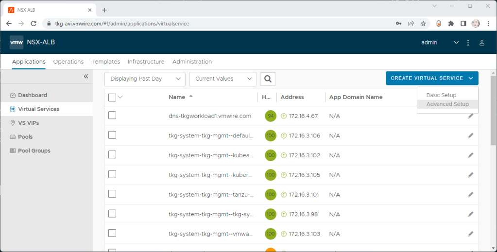
Click on Applications | Virtual Services | Create Virtual Service | Advanced Setup

Select the Cloud to create the DNS virtual service in.

Under Application Profile, select System DNS.

Under VS VIP, click on Create VS VIP.

Press the ADD button under VIPs.

Give the service a name, select a VIP Address Allocation Network, IPv4 Subnet and Placement Network. Don’t set anything for DNS or RBAC.

Then press Save a few times to complete the wizard.

Goto the Advanced tab and choose a Service Engine Group for the DNS service to use.

Press Save to complete the virtual service setup.

Step 2- Enable DNS Service for Avi

Navigate to the Administration tab and select the DNS Virtual Service in the drop-down menu.

Step 3- Edit the default DNS Profile

Navigate to the Templates tab and edit the default DNS profile, the type is Avi Vantage DNS.

Under DNS Service Domains, add in the domain that you will be delegated by the Avi DNS Service. Then press Save.

Step 4- Edit the default DNS Profile

Navigate to the Infrastructure tab and edit the cloud that you want to enable for Avi DNS.

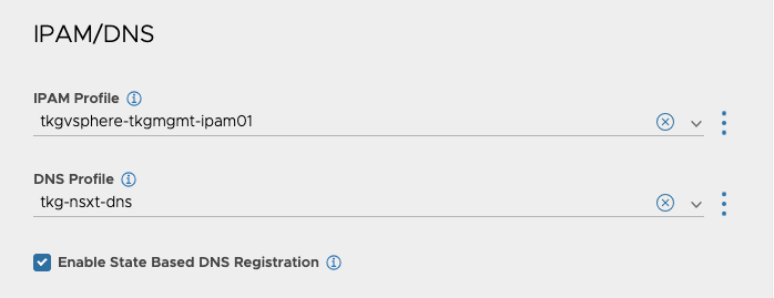
Click on the IPAM/DNS button at the top and it should take you to that section.

Make sure that the DNS profile is selected under DNS Profile.

Step 5- Add the Avi DNS Service as a delegated domain in DNS

Find out the IP address of the Avi DNS virtual service, mine is 172.16.4.67.

You can identify it by going to Applications | Virtual Services.

I use Microsoft DNS Services, so using DNS Manager for the DNS Delegation. I want to use *.tkg-workload1.vmwire.com with Avi Ingress, so to delegate the tkg-workload1 domain with Microsoft DNS Services we create a new Delegation.

Enter the IP address for the FQDN.

Thats it!

You’re now ready for Avi to manage DNS records for the sub domain delegation.

Using Contour to expose Grafana and Prometheus with TLS

The Tanzu Packages in Tanzu Kubernetes Grid (TKG) include Contour, Grafana and Prometheus. Tanzu Packages automatically install and create TLS if ingress is enabled. This post, shows how to update the prometheus-data-values.yaml and grafana-data-values.yaml files to use TLS certificates with ingress using Contour.

This post can be used for TKG on vSphere and CSE with VCD. The examples below use TKG with CSE 4.0.3.

Install Contour

List available contour packages

tanzu package available list contour.tanzu.vmware.com -A

We shall install the latest version available for TKG 1.6.1 used by CSE 4.0.3, 1.20.2+vmware.2-tkg.1. First we need a contour-data-values.yaml file to use to install contour.

If you want to use a static IP address for the envoy load balancer service, for example to re-use the external public IP address currently used by the Kube API you can add a line under line 12:

LoadBalancerIP: <external-ip>

---
infrastructure_provider: vsphere
namespace: tanzu-system-ingress
contour:
 configFileContents: {}
 useProxyProtocol: false
 replicas: 2
 pspNames: "vmware-system-restricted"
 logLevel: info
envoy:
 service:
   type: LoadBalancer
   annotations: {}
   labels: {}
   nodePorts:
     http: null
     https: null
   externalTrafficPolicy: Cluster
   disableWait: false
 hostPorts:
   enable: true
   http: 80
   https: 443
 hostNetwork: false
 terminationGracePeriodSeconds: 300
 logLevel: info
 pspNames: null
certificates:
 duration: 8760h
 renewBefore: 360h

Then install with this command

kubectl create ns my-packages
tanzu package install contour \
--package contour.tanzu.vmware.com \
--version 1.20.2+vmware.2-tkg.1 \
--values-file /home/contour/contour-data-values.yaml \
--namespace my-packages

Install Prometheus

tanzu package available list prometheus.tanzu.vmware.com -A

The latest available version for TKG 1.6.1 used by CSE 4.0.3 is 2.36.2+vmware.1-tkg.1.

Update your prometheus-data-values.yaml file with the TLS certificate, private key, enable ingress and update the virtual_host_fqdn. Use pipe “|” to include all lines of your certificate.

ingress:
  annotations:
    service.beta.kubernetes.io/vcloud-avi-ssl-no-termination: "true"
  alertmanager_prefix: /alertmanager/
  alertmanagerServicePort: 80
  enabled: true
  prometheus_prefix: /
  prometheusServicePort: 80
  tlsCertificate:
    tls.crt: |
      -----BEGIN CERTIFICATE-----
      MIIEZDCCA0ygAwIBAgISA1UHbwcEhpImsiCGFwSMTVQsMA0GCSqGSIb3DQEBCwUA
      MDIxCzAJBgNVBAYTAlVTMRYwFAYDVQQKEw1MZXQncyBFbmNyeXB0MQswCQYDVQQD
      -- snipped --
      -----END CERTIFICATE-----
    tls.key: |

    ca.crt:
  virtual_host_fqdn: prometheus.tenant1.vmwire.com

Install Prometheus with this command

tanzu package install prometheus \
--package prometheus.tanzu.vmware.com \
--version 2.36.2+vmware.1-tkg.1 \
--values-file prometheus-data-values.yaml \
--namespace my-packages

Install Grafana

List available Grafana packages

tanzu package available list grafana.tanzu.vmware.com -A

The latest available version for TKG 1.6.1 used by CSE 4.0.3 is 7.5.7+vmware.2-tkg.1.

Update your grafana-data-values.yaml file with the TLS certificate, private key, enable ingress and update the virtual_host_fqdn. Use pipe “|” to include all lines of your certificate.

ingress:
  annotations:
    service.beta.kubernetes.io/vcloud-avi-ssl-no-termination: "true"
  enabled: true
  prefix: /
  servicePort: 80
  virtual_host_fqdn: grafana.tenant1.vmwire.com
  tlsCertificate:
    tls.crt: |
      -----BEGIN CERTIFICATE-----
      MIIEZDCCA0ygAwIBAgISA1UHbwcEhpImsiCGFwSMTVQsMA0GCSqGSIb3DQEBCwUA
      MDIxCzAJBgNVBAYTAlVTMRYwFAYDVQQKEw1MZXQncyBFbmNyeXB0MQswCQYDVQQD
      --snipped--
      -----END CERTIFICATE-----
    tls.key: |
      -----BEGIN PRIVATE KEY-----
      
      -----END PRIVATE KEY-----

Install Grafana with this command

tanzu package install grafana \
--package grafana.tanzu.vmware.com \
--version 7.5.7+vmware.2-tkg.1 \
--values-file grafana-data-values.yaml \
--namespace my-packages

Update DNS records

Update DNS records for the FQDNs to point to the IP address of the envoy service. You can find the External IP address used by Envoy by typing

k get svc -n tanzu-system-ingress envoy.

Using Contour for KubeApps with TLS

Kubeapps provides a cloud native solution to browse, deploy and manage the lifecycle of applications on a Kubernetes cluster. The very basic installation of KubeApps does not expose the application outside of the Kubernetes cluster as the default service type is ClusterIP.

You can easily expose using a LoadBalancer service but the application will use a self-signed certificate.

This post shows you how you can expose using Contour ingress instead and use a TLS certificate to secure access.

Deploy KubeApps

You’ll need to have Contour installed before installing KubeApps.

Deploy KubeApps as normal using Helm.

helm repo add bitnami https://charts.bitnami.com/bitnami
kubectl create namespace kubeapps
helm install kubeapps --namespace kubeapps bitnami/kubeapps

Create a demo credential to access KubeApps

kubectl create --namespace default serviceaccount kubeapps-operator
kubectl create clusterrolebinding kubeapps-operator --clusterrole=cluster-admin --serviceaccount=default:kubeapps-operator
cat <<EOF | kubectl apply -f -
apiVersion: v1
kind: Secret
metadata:
  name: kubeapps-operator-token
  namespace: default
  annotations:
    kubernetes.io/service-account.name: kubeapps-operator
type: kubernetes.io/service-account-token
EOF


Create Contour HTTPProxy and Kubernetes-tls secret

Use this manifest to create a kubernetes-tls secret and httpproxy to use with Contour.

Paste in the tls.crt and tls.key in base64 format and update the fqdn.

kubeapps-contour.yaml

apiVersion: projectcontour.io/v1
kind: HTTPProxy
metadata:
  name: kubeapps-grpc
  namespace: kubeapps
spec:
  virtualhost:
    fqdn: kubeapps.tenant1.vmwire.com
    tls:
      secretName: kubeapps-host-tls
  routes:
    - conditions:
      - prefix: /apis/
      pathRewritePolicy:
        replacePrefix:
        - replacement: /
      services:
        - name: kubeapps-internal-kubeappsapis
          port: 8080
          protocol: h2c
    - services:
      - name: kubeapps
        port: 80
---
apiVersion: v1
data:
  tls.crt: |
    ---snipped---
  tls.key: |

kind: Secret
metadata:
  name: kubeapps-host-tls
  namespace: kubeapps
type: kubernetes.io/tls

Then apply the manifest to create the secret and httpproxy with kubectl apply -f kubeapps-contour.yaml.

Update DNS

Update DNS records for the FQDNs to point to the IP address of the envoy service. You can find the External IP address used by Envoy by typing kubectl get svc -n tanzu-system-ingress envoy.

Obtain token and login

Obtain the token to login kubectl get --namespace default secret kubeapps-operator-token -o go-template='{{.data.token | base64decode}}'

Open up a browser session and enter the FQDN of the virtual host. You should now be able to log into KubeApps and enjoy a secure TLS connection too.

Single node clusters with TKG

Single-node clusters are a Tech Preview for TKG since 2.1 on vSphere. Its not actually a single-node cluster per-se but a collapsed Kubernetes node with both the control plane and the worker node on one virtual machine that can be deployed in a cluster with more than one node or just as a single-node.

Use cases include edge deployments or hardware constrained environments.

You can deploy a single node or three nodes that has both the control plane and the worker node roles. In fact, to Kubernetes, the node is recognised as a control plane node, but pods are allowed to be scheduled on the nodes since we change the spec.topology.variables.controlPlaneTaint=false in the cluster config specification.

A few things to know about single node clusters

  • Supported on TKG 2.1 and newer with the standalone management cluster only, not supported with vSphere with Tanzu (TKG with Supervisor).
  • Single node clusters are supported with Cluster Class based clusters only. Legacy clusters are not supported.
  • Single node clusters behave just like any other TKG clusters so it will support everything you are used to.
  • You can deploy nodes that are both control plane and workers in only odd numbers, this is because Kubernetes still treats these nodes as control plane nodes, but allow any pod to be scheduled on them. So scaling the cluster up from one node to 3, 5, 7 etc is possible with a simple one line command of tanzu cluster scale <cluster-name> -c #. Here is a cluster with five nodes. As you can see Kubernetes assigns the control-plane role to the nodes. However, deploying a single-node cluster removes the Taints from the node. On any other cluster type you’ll see this taint Taints: node-role.kubernetes.io/control-plane:NoSchedule. This is removed for single-node clusters.
k get no -o wide
NAME                     STATUS   ROLES           AGE     VERSION            INTERNAL-IP   EXTERNAL-IP   OS-IMAGE             KERNEL-VERSION      CONTAINER-RUNTIME
tkg-single-ngbmw-dcljq   Ready    control-plane   17m     v1.25.7+vmware.2   172.16.3.84   172.16.3.84   Ubuntu 20.04.6 LTS   5.4.0-144-generic   containerd://1.6.18-1-gdbc99e5b1
tkg-single-ngbmw-mm6tp   Ready    control-plane   9m51s   v1.25.7+vmware.2   172.16.3.85   172.16.3.85   Ubuntu 20.04.6 LTS   5.4.0-144-generic   containerd://1.6.18-1-gdbc99e5b1
tkg-single-ngbmw-mvdv2   Ready    control-plane   14m     v1.25.7+vmware.2   172.16.3.70   172.16.3.70   Ubuntu 20.04.6 LTS   5.4.0-144-generic   containerd://1.6.18-1-gdbc99e5b1
tkg-single-ngbmw-ngqxd   Ready    control-plane   12m     v1.25.7+vmware.2   172.16.3.75   172.16.3.75   Ubuntu 20.04.6 LTS   5.4.0-144-generic   containerd://1.6.18-1-gdbc99e5b1
tkg-single-ngbmw-tqq79   Ready    control-plane   3h1m    v1.25.7+vmware.2   172.16.3.82   172.16.3.82   Ubuntu 20.04.6 LTS   5.4.0-144-generic   containerd://1.6.18-1-gdbc99e5b1
  • You can also scale down
k get no
NAME                     STATUS   ROLES           AGE   VERSION
tkg-single-ngbmw-mm6tp   Ready    control-plane   18m   v1.25.7+vmware.2
  • You can register single node clusters to TMC. This is possible as TKG changes the metadata for single node clusters as a workload cluster type. You can find this by looking at the config map for the tkg-metadata k get cm -n tkg-system-public tkg-metadata -o yaml. Line 6 below.
apiVersion: v1
data:
  metadata.yaml: |
    cluster:
        name: tkg-single
        type: workload
        plan: dev
        kubernetesProvider: VMware Tanzu Kubernetes Grid
        tkgVersion: v2.2.0
        edition: tkg
        infrastructure:
            provider: vsphere
        isClusterClassBased: true
    bom:
        configmapRef:
            name: tkg-bom
kind: ConfigMap
metadata:
  creationTimestamp: "2023-05-29T14:47:14Z"
  name: tkg-metadata
  namespace: tkg-system-public
  resourceVersion: "250"
  uid: 944a120b-595c-4367-a570-db295af54d11

To deploy a single-node cluster, you can refer to the documentation here.

  • In summary, switch to the TKG management cluster context and type this command to enable single-node clusters tanzu config set features.cluster.single-node-clusters true
  • create a cluster config file as normal, and save the file as a yaml, for example tkg-single.yaml.
#! ---------------------------------------------------------------------
#! Basic cluster creation configuration
#! ---------------------------------------------------------------------

# CLUSTER_NAME:
ALLOW_LEGACY_CLUSTER: false
INFRASTRUCTURE_PROVIDER: vsphere
CLUSTER_PLAN: dev
NAMESPACE: default
# CLUSTER_API_SERVER_PORT: # For deployments without NSX Advanced Load Balancer
CNI: antrea
ENABLE_DEFAULT_STORAGE_CLASS: false

#! ---------------------------------------------------------------------
#! Node configuration
#! ---------------------------------------------------------------------

# SIZE:
#CONTROLPLANE_SIZE: small
#WORKER_SIZE: small

# VSPHERE_NUM_CPUS: 2
# VSPHERE_DISK_GIB: 40
# VSPHERE_MEM_MIB: 4096

VSPHERE_CONTROL_PLANE_NUM_CPUS: 4
VSPHERE_CONTROL_PLANE_DISK_GIB: 40
VSPHERE_CONTROL_PLANE_MEM_MIB: 8192
# VSPHERE_WORKER_NUM_CPUS: 2
# VSPHERE_WORKER_DISK_GIB: 40
# VSPHERE_WORKER_MEM_MIB: 4096

# CONTROL_PLANE_MACHINE_COUNT:
# WORKER_MACHINE_COUNT:
# WORKER_MACHINE_COUNT_0:
# WORKER_MACHINE_COUNT_1:
# WORKER_MACHINE_COUNT_2:

#! ---------------------------------------------------------------------
#! vSphere configuration
#! ---------------------------------------------------------------------

#VSPHERE_CLONE_MODE: "fullClone"
VSPHERE_NETWORK: tkg-workload
# VSPHERE_TEMPLATE:
# VSPHERE_TEMPLATE_MOID:
# IS_WINDOWS_WORKLOAD_CLUSTER: false
# VIP_NETWORK_INTERFACE: "eth0"
VSPHERE_SSH_AUTHORIZED_KEY: <-- snipped -->
VSPHERE_USERNAME: administrator@vsphere.local
VSPHERE_PASSWORD: 
# VSPHERE_REGION:
# VSPHERE_ZONE:
# VSPHERE_AZ_0:
# VSPHERE_AZ_1:
# VSPHERE_AZ_2:
# USE_TOPOLOGY_CATEGORIES: false
VSPHERE_SERVER: vcenter.vmwire.com
VSPHERE_DATACENTER: home.local
VSPHERE_RESOURCE_POOL: tkg-vsphere-workload
VSPHERE_DATASTORE: lun01
VSPHERE_FOLDER: tkg-vsphere-workload
# VSPHERE_STORAGE_POLICY_ID
# VSPHERE_WORKER_PCI_DEVICES:
# VSPHERE_CONTROL_PLANE_PCI_DEVICES:
# VSPHERE_IGNORE_PCI_DEVICES_ALLOW_LIST:
VSPHERE_CONTROL_PLANE_CUSTOM_VMX_KEYS: 'ethernet0.ctxPerDev=3,ethernet0.pnicFeatures=4,sched.cpu.shares=high'
# VSPHERE_WORKER_CUSTOM_VMX_KEYS: 'ethernet0.ctxPerDev=3,ethernet0.pnicFeatures=4,sched.cpu.shares=high'
# WORKER_ROLLOUT_STRATEGY: "RollingUpdate"
# VSPHERE_CONTROL_PLANE_HARDWARE_VERSION:
# VSPHERE_WORKER_HARDWARE_VERSION:
VSPHERE_TLS_THUMBPRINT: <-- snipped -->
VSPHERE_INSECURE: false
# VSPHERE_CONTROL_PLANE_ENDPOINT: # Required for Kube-Vip
# VSPHERE_CONTROL_PLANE_ENDPOINT_PORT: 6443
# VSPHERE_ADDITIONAL_FQDN:
AVI_CONTROL_PLANE_HA_PROVIDER: true


#! ---------------------------------------------------------------------
#! Common configuration
#! ---------------------------------------------------------------------

ADDITIONAL_IMAGE_REGISTRY_1: "harbor.vmwire.com"
ADDITIONAL_IMAGE_REGISTRY_1_SKIP_TLS_VERIFY: false
ADDITIONAL_IMAGE_REGISTRY_1_CA_CERTIFICATE: <-- snipped -->


# TKG_CUSTOM_IMAGE_REPOSITORY: ""
# TKG_CUSTOM_IMAGE_REPOSITORY_SKIP_TLS_VERIFY: false
# TKG_CUSTOM_IMAGE_REPOSITORY_CA_CERTIFICATE: ""

# TKG_HTTP_PROXY: ""
# TKG_HTTPS_PROXY: ""
# TKG_NO_PROXY: ""
# TKG_PROXY_CA_CERT: ""

ENABLE_AUDIT_LOGGING: false

CLUSTER_CIDR: 100.96.0.0/11
SERVICE_CIDR: 100.64.0.0/13

# OS_NAME: ""
# OS_VERSION: ""
# OS_ARCH: ""

#! ---------------------------------------------------------------------
#! Autoscaler configuration
#! ---------------------------------------------------------------------

ENABLE_AUTOSCALER: false

Then use the –dry-run option and save the cluster object spec file with tanzu cluster create <name-of-new-cluster> -f tkg-single.yaml > tkg-single-spec.yaml --dry-run, this creates a new file called tkg-single-spec.yaml that you need to edit before creating the single node cluster.

Edit the tkg-single-spec.yaml file and change the following sections.

under spec.topology.variables, add the following:

- name: controlPlaneTaint
  value: false

under spec.topology.workers, delete the entire block including the workers section heading.

Your changed file should look like the example below.

apiVersion: csi.tanzu.vmware.com/v1alpha1
kind: VSphereCSIConfig
metadata:
  name: tkg-single
  namespace: default
spec:
  vsphereCSI:
    config:
      datacenter: /home.local
      httpProxy: ""
      httpsProxy: ""
      noProxy: ""
      region: null
      tlsThumbprint: <-- snipped -->
      useTopologyCategories: false
      zone: null
    mode: vsphereCSI
---
apiVersion: run.tanzu.vmware.com/v1alpha3
kind: ClusterBootstrap
metadata:
  annotations:
    tkg.tanzu.vmware.com/add-missing-fields-from-tkr: v1.25.7---vmware.2-tkg.1
  name: tkg-single
  namespace: default
spec:
  additionalPackages:
  - refName: metrics-server*
  - refName: secretgen-controller*
  - refName: pinniped*
  - refName: tkg-storageclass*
    valuesFrom:
      inline:
        infraProvider: ""
  csi:
    refName: vsphere-csi*
    valuesFrom:
      providerRef:
        apiGroup: csi.tanzu.vmware.com
        kind: VSphereCSIConfig
        name: tkg-single
  kapp:
    refName: kapp-controller*
---
apiVersion: v1
kind: Secret
metadata:
  name: tkg-single
  namespace: default
stringData:
  password: 
  username: administrator@vsphere.local
---
apiVersion: cluster.x-k8s.io/v1beta1
kind: Cluster
metadata:
  annotations:
    osInfo: ubuntu,20.04,amd64
    tkg/plan: dev
  labels:
    tkg.tanzu.vmware.com/cluster-name: tkg-single
  name: tkg-single
  namespace: default
spec:
  clusterNetwork:
    pods:
      cidrBlocks:
      - 100.96.0.0/11
    services:
      cidrBlocks:
      - 100.64.0.0/13
  topology:
    class: tkg-vsphere-default-v1.0.0
    controlPlane:
      metadata:
        annotations:
          run.tanzu.vmware.com/resolve-os-image: image-type=ova,os-name=ubuntu
      replicas: 1
    variables:
    - name: controlPlaneTaint
      value: false
    - name: cni
      value: antrea
    - name: controlPlaneCertificateRotation
      value:
        activate: true
        daysBefore: 90
    - name: additionalImageRegistries
      value:
      - caCert: <-- snipped -->
        host: harbor.vmwire.com
        skipTlsVerify: false
    - name: auditLogging
      value:
        enabled: false
    - name: podSecurityStandard
      value:
        audit: baseline
        deactivated: false
        warn: baseline
    - name: aviAPIServerHAProvider
      value: true
    - name: vcenter
      value:
        cloneMode: fullClone
        datacenter: /home.local
        datastore: /home.local/datastore/lun01
        folder: /home.local/vm/tkg-vsphere-workload
        network: /home.local/network/tkg-workload
        resourcePool: /home.local/host/cluster/Resources/tkg-vsphere-workload
        server: vcenter.vmwire.com
        storagePolicyID: ""
        template: /home.local/vm/Templates/ubuntu-2004-efi-kube-v1.25.7+vmware.2
        tlsThumbprint: <-- snipped -->
    - name: user
      value:
        sshAuthorizedKeys:
        - <-- snipped -->
    - name: controlPlane
      value:
        machine:
          customVMXKeys:
            ethernet0.ctxPerDev: "3"
            ethernet0.pnicFeatures: "4"
            sched.cpu.shares: high
          diskGiB: 40
          memoryMiB: 8192
          numCPUs: 4
    - name: worker
      value:
        count: 1
        machine:
          diskGiB: 40
          memoryMiB: 4096
          numCPUs: 2
    version: v1.25.7+vmware.2-tkg.1

AviInfraSetting with IngressClass

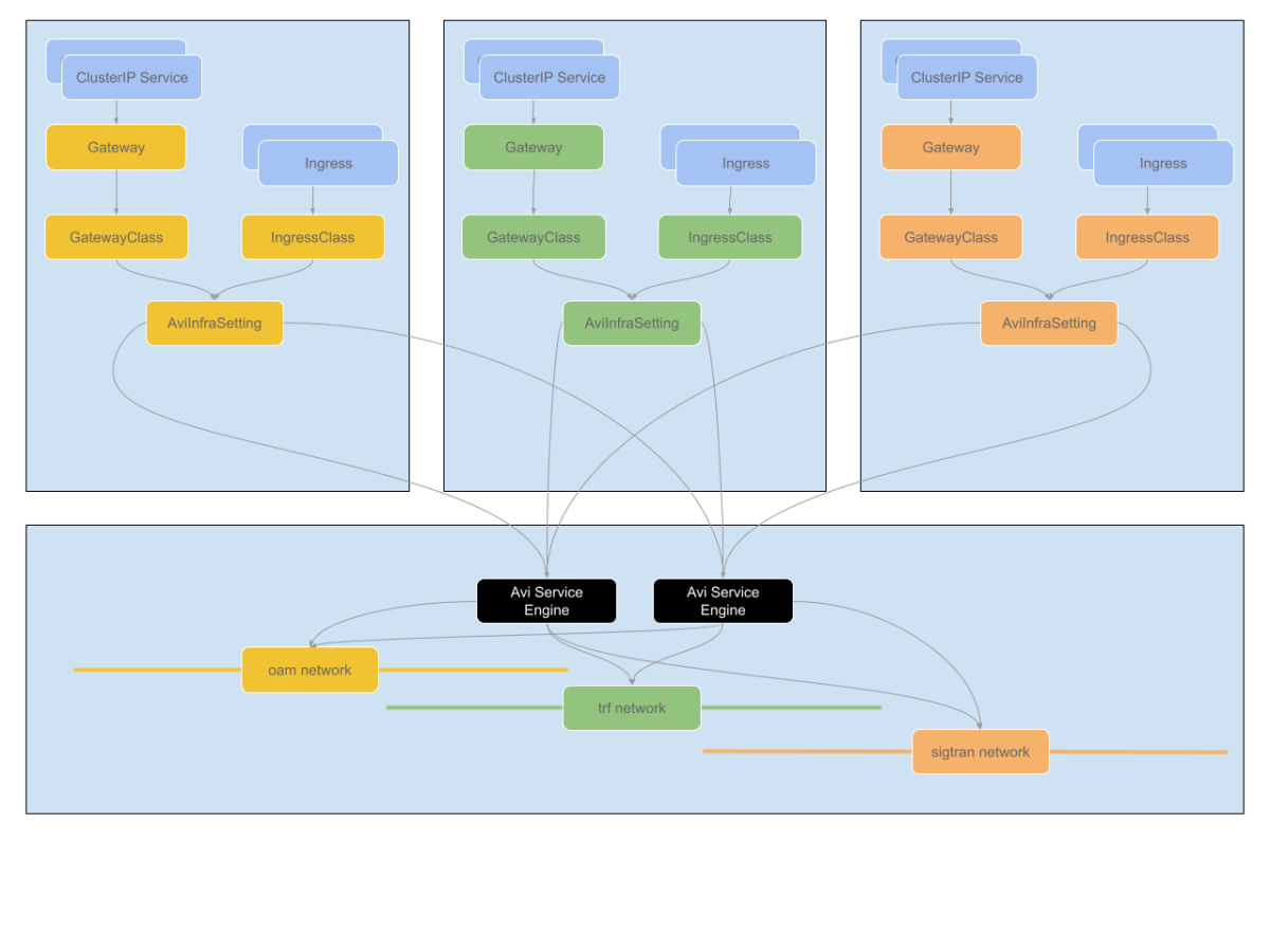
Avi Infra Setting provides a way to segregate Layer-4/Layer-7 virtual services to have properties based on different underlying infrastructure components, like Service Engine Group, intended VIP Network etc.

Here I have a different network that I want a new Ingress to use, in this case the tkg-wkld-trf-vip network, 172.16.4.97/27, lets assume its used for 5G traffic connectivity and the NSX-T T1 is connected to a different T0 VRF. This isolates the traffic between VRFs, so that we can expose certain applications on different VRFs.

In this example, I’ll change Grafana from using the default VIP network to the tkg-wkld-trf-vip network instead. You can read up on how this was originally done using the default VIP network in the previous post.

aviinfrasetting-tkg-wkld-trf-vip.yaml

---
apiVersion: ako.vmware.com/v1alpha1
kind: AviInfraSetting
metadata:
  name: aviinfrasetting-tkg-wkld-trf-vip
spec:
  seGroup:
    name: tkg-workload1
  network:
    vipNetworks:
      - networkName: tkg-wkld-trf-vip
        cidr: 172.16.4.96/27
    enableRhi: false

Attaching Avi Infra Setting to Ingress

Avi Infra Settings can be applied to Ingress resources, using the IngressClass construct. IngressClass provides a way to configure Controller-specific load balancing parameters and applies these configurations to a set of Ingress objects. AKO supports listening to IngressClass resources in Kubernetes version 1.19+. The Avi Infra Setting reference can be provided in the Ingress Class as shown below:

aviingressclass-tkg-wkld-trf-vip.yaml

---
apiVersion: networking.k8s.io/v1
kind: IngressClass
metadata:
  name: aviingressclass-tkg-wkld-trf-vip
spec:
  controller: ako.vmware.com/avi-lb
  parameters:
    apiGroup: ako.vmware.com
    kind: AviInfraSetting
    name: aviinfrasetting-tkg-wkld-trf-vip

dashboard-ingress.yaml

---
apiVersion: networking.k8s.io/v1
kind: Ingress
metadata:
  name: dashboard-ingress
  namespace: tanzu-system-dashboards
  annotations:
    ako.vmware.com/enable-tls: "true"
  labels:
    app: dashboard-ingress
spec:
  ingressClassName: aviingressclass-tkg-wkld-trf-vip
  rules:
    - host: "grafana.tkg-workload1.vmwire.com"
      http:
        paths:
          - pathType: Prefix
            path: /
            backend:
              service:
                name: grafana
                port:
                  number: 80

Below you can see that Grafana is now using the new AviInfraSetting and has been assigned an IP address of 172.16.4.98.

Introduction to Avi Ingress and Replacing Contour for Prometheus and Grafana

Avi Ingress is an alternative to Contour and NGINX ingress controllers.

Tanzu Kubernetes Grid ships with Contour as the default Ingress controller that Tanzu Packages uses to expose Prometheus and Contour. Prometheus and Grafana are configured to use Contour if you set ingress: true in the values.yaml files.

This post details how to set Avi Ingress up and use it to expose these applications using signed TLS certificates.

Let’s start

Install AKO with helm as normal, use ClusterIP in the Avi values.yaml config file.

Reference link to documentation:

https://avinetworks.com/docs/ako/1.9/networking-v1-ingress/

Create secret for ingress certificate, using a wildcard certificate will enable Avi to automatically secure all applications with the TLS certificate.

tls.key and tls.crt in base64 encoded format.

router-certs-default.yaml

apiVersion: v1
kind: Secret
metadata:
  name: router-certs-default
  namespace: avi-system
type: kubernetes.io/tls
data:
  tls.key: --snipped--
  tls.crt: LS0tLS1CRUdJTiBDRVJUSUZJQ0FURS0tLS0tCk1JSUVjVENDQTFtZ0F3SUJBZ0lTQTI0MDJNMStJN01kaTIwRWZlK2hlQitQTUEwR0NTcUdTSWIzRFFFQkN3VUEKTURJeEN6QUpCZ05WQkFZVEFsVlRNUll3RkFZRFZRUUtFdzFNWlhRbmN5QkZibU55ZVhCME1Rc3dDUVlEVlFRRApFd0pTTXpBZUZ3MHlNekF6TWpReE1qSTBNakphRncweU16QTJNakl4TWpJME1qRmFNQ1V4SXpBaEJnTlZCQU1NCkdpb3VkR3RuTFhkdmNtdHNiMkZrTVM1MmJYZHBjbVV1WTI5dE1Ga3dFd1lIS29aSXpqMENBUVlJS29aSXpqMEQKQVFjRFFnQUVmcEs2MUQ5bFkyQUZzdkdwZkhwRlNEYVl1alF0Nk05Z21yYUhrMG5ySHJhTUkrSEs2QXhtMWJyRwpWMHNrd2xDWEtrWlNCbzRUZmFlTDF6bjI1N0M1QktPQ0FsY3dnZ0pUTUE0R0ExVWREd0VCL3dRRUF3SUhnREFkCkJnTlZIU1VFRmpBVUJnZ3JCZ0VGQlFjREFRWUlLd1lCQlFVSEF3SXdEQVlEVlIwVEFRSC9CQUl3QURBZEJnTlYKSFE0RUZnUVVxVjMydlU4Yzl5RFRpY3NVQmJCMFE0MFNsZFl3SHdZRFZSMGpCQmd3Rm9BVUZDNnpGN2RZVnN1dQpVQWxBNWgrdm5Zc1V3c1l3VlFZSUt3WUJCUVVIQVFFRVNUQkhNQ0VHQ0NzR0FRVUZCekFCaGhWb2RIUndPaTh2CmNqTXVieTVzWlc1amNpNXZjbWN3SWdZSUt3WUJCUVVITUFLR0ZtaDBkSEE2THk5eU15NXBMbXhsYm1OeUxtOXkKWnk4d0pRWURWUjBSQkI0d0hJSWFLaTUwYTJjdGQyOXlhMnh2WVdReExuWnRkMmx5WlM1amIyMHdUQVlEVlIwZwpCRVV3UXpBSUJnWm5nUXdCQWdFd053WUxLd1lCQkFHQzN4TUJBUUV3S0RBbUJnZ3JCZ0VGQlFjQ0FSWWFhSFIwCmNEb3ZMMk53Y3k1c1pYUnpaVzVqY25sd2RDNXZjbWN3Z2dFR0Jnb3JCZ0VFQWRaNUFnUUNCSUgzQklIMEFQSUEKZHdCNk1veFUyTGN0dGlEcU9PQlNIdW1FRm5BeUU0Vk5POUlyd1RwWG8xTHJVZ0FBQVljVHlxNTJBQUFFQXdCSQpNRVlDSVFEekZNSklaT3NKMG9GQTV2UVVmNUpZQUlaa3dBMnkxNE92K3ljcTU0ZDZmZ0loQUxOcmNnM0lrNllsCkxlMW1ROHFVZmttNWsxRTZBSDU4OFJhYWZkZlhONTJCQUhjQTZEN1EyajcxQmpVeTUxY292SWxyeVFQVHk5RVIKYSt6cmFlRjNmVzBHdlc0QUFBR0hFOHF1VlFBQUJBTUFTREJHQWlFQW9Wc3ZxbzhaR2o0cmszd1hmL0xlSkNCbApNQkg2UFpBb2UyMVVkbko5aThvQ0lRRGoyS1Q1eWlUOGtRdjFyemxXUWgveHV6VlRpUGtkdlBHL3Zxd3J0SWhjCjJEQU5CZ2txaGtpRzl3MEJBUXNGQUFPQ0FRRUFFczlKSTFwZ3R6T2JyRmd0Vnpsc1FuZC8xMi9QYWQ5WXI2WVMKVE5XM3F1bElhaEZ4UDdVcVRIT0xVSGw0cGdpTThxZ2ZlcmhyTHZXbk1wOUlxQ3JVVElTSnFRblh5bnkyOHA2Zwoyc2NqS2xFSWt2RURvcExoek0ydGpCenc4a1dUYUdYUE8yM0dhcHBHWW14OS9Ma2NkUDVSS0xKMmlRTEJXZlhTCmNQRlNmZWsySEc3dEw1N0s0Uit4eDB4MTdsZ2RLeFdOL1JYQ2RvcHFPY3RyTCtPL0lwWVVWZXNiVzNJbkpFZDkKdjZmS1RmVE84K3JVVnlkajVmUGdFUWJva2Q2L3BDTGdIYS81UVpQMjZ1ZytRa1llUEJvUWRrTkpGOTk4a2NHWQpBZGc0THpJZjdYdU9SNDB4eU90aHIyN1p4Y1FXZnhMM2M4bGJuUlJrMXZNL3pMMDhIdz09Ci0tLS0tRU5EIENFUlRJRklDQVRFLS0tLS0=

k apply -f router-certs-default.yaml

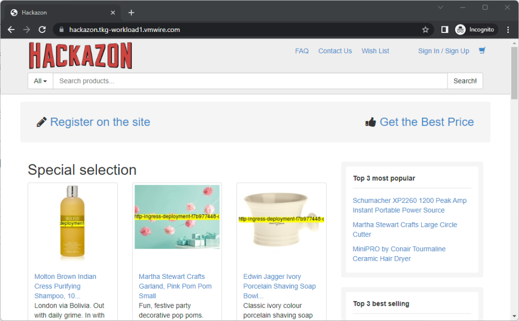
Here is the example online store website deployment using ingress with the certificate. Lets play with this before we get around to exposing Prometheus and Grafana.

sample-ingress.yaml

---
kind: Deployment
apiVersion: apps/v1
metadata:
  name: http-ingress-deployment
  labels:
    app: http-ingress
spec:
  replicas: 1
  selector:
    matchLabels:
      app: http-ingress
  template:
    metadata:
      labels:
        app: http-ingress
    spec:
      containers:
        - name: http-ingress
          image: ianwijaya/hackazon
          ports:
            - name: http
              containerPort: 80
              protocol: TCP
      imagePullSecrets:
      - name: regcred
---
kind: Service
apiVersion: v1
metadata:
  name: ingress-svc
  labels:
    svc: ingress-svc
spec:
  ports:
    - name: http
      port: 80
      targetPort: 80
  selector:
    app: http-ingress
  type: ClusterIP

avisvcingress.yaml

---
apiVersion: networking.k8s.io/v1
kind: Ingress
metadata:
  name: avisvcingress
  annotations:
    ako.vmware.com/enable-tls: "true"
  labels:
    app: avisvcingress
spec:
  ingressClassName: avi-lb
  rules:
    - host: "hackazon.tkg-workload1.vmwire.com"
      http:
        paths:
          - pathType: Prefix
            path: /
            backend:
              service:
                name: ingress-svc
                port:
                  number: 80

Note that the Service uses ClusterIP and the Ingress is annotated with ako.vmware.com/enable-tls: "true" to use the default tls specified in router-certs-default.yaml. Also add the ingressClassName into the Ingress manifest.

k apply -f sample-ingress.yaml

k apply -f avisvcingress.yaml

k get ingress avisvcingress

NAME CLASS HOSTS ADDRESS PORTS AGE
avisvcingress avi-lb hackazone.tkg-workload1.vmwire.com 172.16.4.69 80 13m

Let’s add another host

Append another host to the avisvcingress.yaml file.

---
apiVersion: networking.k8s.io/v1
kind: Ingress
metadata:
  name: avisvcingress
  annotations:
    ako.vmware.com/enable-tls: "true"
  labels:
    app: avisvcingress
spec:
  ingressClassName: avi-lb
  rules:
    - host: "hackazon.tkg-workload1.vmwire.com"
      http:
        paths:
          - pathType: Prefix
            path: /
            backend:
              service:
                name: ingress-svc
                port:
                  number: 80
    - host: "nginx.tkg-workload1.vmwire.com"
      http:
        paths:
          - pathType: Prefix
            path: /
            backend:
              service:
                name: nginx-service
                port:
                  number: 80

k replace -f avisvcingress.yaml

And use the trusty statefulset file to create an nginx webpage. statefulset-topology-aware.yaml

---
apiVersion: v1
kind: Service
metadata:
  name: nginx-service
  namespace: default
  labels:
spec:
  selector:
    app: nginx
  ports:
    - port: 80
      targetPort: 80
      protocol: TCP
  type: ClusterIP
---
apiVersion: apps/v1
kind: StatefulSet
metadata:
  name: web
spec:
  replicas: 3
  selector:
    matchLabels:
      app: nginx
  serviceName: nginx-service
  template:
    metadata:
      labels:
        app: nginx
    spec:
      affinity:
        nodeAffinity:
          requiredDuringSchedulingIgnoredDuringExecution:
            nodeSelectorTerms:
            - matchExpressions:
              - key: failure-domain.beta.kubernetes.io/zone
                operator: In
                values:
                - az-1
                - az-2
                - az-3
        podAntiAffinity:
          requiredDuringSchedulingIgnoredDuringExecution:
          - labelSelector:
              matchExpressions:
              - key: app
                operator: In
                values:
                - nginx
            topologyKey: failure-domain.beta.kubernetes.io/zone
      terminationGracePeriodSeconds: 10
      initContainers:
      - name: install
        image: busybox
        command:
        - wget
        - "-O"
        - "/www/index.html"
        - https://raw.githubusercontent.com/hugopow/cse/main/index.html
        volumeMounts:
        - name: www
          mountPath: "/www"
      containers:
        - name: nginx
          image: k8s.gcr.io/nginx-slim:0.8
          ports:
            - containerPort: 80
              name: web
          volumeMounts:
            - name: www
              mountPath: /usr/share/nginx/html
            - name: logs
              mountPath: /logs
  volumeClaimTemplates:
    - metadata:
        name: www
      spec:
        accessModes: [ "ReadWriteOnce" ]
        storageClassName: tanzu-local-ssd
        resources:
          requests:
            storage: 2Gi
    - metadata:
        name: logs
      spec:
        accessModes: [ "ReadWriteOnce" ]
        storageClassName: tanzu-local-ssd
        resources:
          requests:
            storage: 1Gi

k apply -f statefulset-topology-aware.yaml

k get ingress avisvcingress

NAME            CLASS    HOSTS                                                             ADDRESS       PORTS   AGE
avisvcingress   avi-lb   hackazon.tkg-workload1.vmwire.com,nginx.tkg-workload1.vmwire.com   172.16.4.69   80      7m33s

Notice that another host is added to the same ingress, and both hosts share the same VIP.

Lets add Prometheus to this!

Create a new manifest for Prometheus to use called monitoring-ingress.yaml

---
apiVersion: networking.k8s.io/v1
kind: Ingress
metadata:
  name: monitoring-ingress
  namespace: tanzu-system-monitoring
  annotations:
    ako.vmware.com/enable-tls: "true"
  labels:
    app: monitoring-ingress
spec:
  ingressClassName: avi-lb
  rules:
    - host: "prometheus.tkg-workload1.vmwire.com"
      http:
        paths:
          - pathType: Prefix
            path: /
            backend:
              service:
                name: prometheus-server
                port:
                  number: 80

Note that since Prometheus when deployed by Tanzu Packages is deployed into the namespace tanzu-system-monitoring, we also need to create the new ingress in the same namespace.

Deploy Prometheus following the documentation here, but do not enable ingress in the prometheus-data-values.yaml file, that uses Contour. We don’t want that as we are using Avi Ingress instead.

Add Grafana too!

Create a new manifest for Grafana to use called dashboard-ingress.yaml.

---
apiVersion: networking.k8s.io/v1
kind: Ingress
metadata:
  name: dashboard-ingress
  namespace: tanzu-system-dashboards
  annotations:
    ako.vmware.com/enable-tls: "true"
  labels:
    app: dashboard-ingress
spec:
  ingressClassName: avi-lb
  rules:
    - host: "grafana.tkg-workload1.vmwire.com"
      http:
        paths:
          - pathType: Prefix
            path: /
            backend:
              service:
                name: grafana
                port:
                  number: 80

Note that since Grafana when deployed by Tanzu Packages is deployed into the namespace tanzu-system-dashboards, we also need to create the new ingress in the same namespace.

Deploy Grafana following the documentation here, but do not enable ingress in the grafana-data-values.yaml file, that uses Contour. We don’t want that as we are using Avi Ingress instead.

Summary

Ingress with Avi is really nice, I like it! A single secret to store the TLS certificates and all hosts are automatically configured to use TLS. You also just need to expose TCP 80 as ClusterIP Services and Avi will do the rest for you and expose the application over TCP 443 using the TLS cert.

Here you can see that all four of our applications – hackazon, nginx running across three AZs, Grafana and Prometheus all using Ingress and sharing a single IP address.

Very cool indeed!

k get ingress -A

NAMESPACE                 NAME                 CLASS    HOSTS                                                              ADDRESS       PORTS   AGE
default                   avisvcingress        avi-lb   hackazon.tkg-workload1.vmwire.com,nginx.tkg-workload1.vmwire.com   172.16.4.69   80      58m
tanzu-system-dashboards   dashboard-ingress    avi-lb   grafana.tkg-workload1.vmwire.com                                   172.16.4.69   80      3m47s
tanzu-system-monitoring   monitoring-ingress   avi-lb   prometheus.tkg-workload1.vmwire.com                                172.16.4.69   80      14m

CSE TKG Clusters can’t pull from GitHub

During TKG cluster creation you might see the following errors.

Error: failed to get
provider components for the "cluster-api:v1.1.3" provider: failed to get
repository client for the CoreProvider with name cluster-api: error creating
the GitHub repository client: failed to get GitHub latest version: failed to
get repository versions: failed to get repository versions: rate limit for
github api has been reached. Please wait one hour or get a personal API
token and assign it to the GITHUB_TOKEN environment variable

This is due to GitHub rate limiting for anonymous access to GitHub. CSE TKG clusters pull images from GitHub, and if you are pulling too many within a short period of time, you will eventually hit the rate limits.

To ensure that you don’t hit the limits a GitHub Access Token is needed.

Then configure CSE to use the GitHub Access Token using the CSE documentation here.

Scaling TKG Management Cluster Nodes Vertically

In a previous post I wrote about how to scale workload cluster control plane and worker nodes vertically. This post explains how to do the same for the TKG Management Cluster nodes.

Scaling vertically is increasing or decreasing the CPU, Memory, Disk or changing other things such as the network for the nodes. Using the Cluster API it is possible to make these changes on the fly, Kubernetes will use rolling updates to make the necessary changes.

First change to the TKG Management Cluster context to make the changes.

Scaling Worker Nodes

Run the following to list all the vSphereMachineTemplates.

k get vspheremachinetemplates.infrastructure.cluster.x-k8s.io -A
NAMESPACE    NAME                         AGE
tkg-system   tkg-mgmt-control-plane       20h
tkg-system   tkg-mgmt-worker              20h

These custom resource definitions are immutable so we will need to make a copy of the yaml file and edit it to add a new vSphereMachineTemplate.

k get vspheremachinetemplates.infrastructure.cluster.x-k8s.io -n tkg-system   tkg-mgmt-worker -o yaml > tkg-mgmt-worker-new.yaml

Now edit the new file named tkg-mgmt-worker-new.yaml

apiVersion: infrastructure.cluster.x-k8s.io/v1beta1
kind: VSphereMachineTemplate
metadata:
  annotations:
    kubectl.kubernetes.io/last-applied-configuration: |
      {"apiVersion":"infrastructure.cluster.x-k8s.io/v1beta1","kind":"VSphereMachineTemplate","metadata":{"annotations":{"vmTemplateMoid":"vm-9726"},"name":"tkg-mgmt-worker","namespace":"tkg-system"},"spec":{"template":{"spec":{"cloneMode":"fullClone","datacenter":"/home.local","datastore":"/home.local/datastore/lun01","diskGiB":40,"folder":"/home.local/vm/tkg-vsphere-tkg-mgmt","memoryMiB":8192,"network":{"devices":[{"dhcp4":true,"networkName":"/home.local/network/tkg-mgmt"}]},"numCPUs":2,"resourcePool":"/home.local/host/Management/Resources/tkg-vsphere-tkg-Mgmt","server":"vcenter.vmwire.com","storagePolicyName":"","template":"/home.local/vm/Templates/photon-3-kube-v1.22.9+vmware.1"}}}}
    vmTemplateMoid: vm-9726
  creationTimestamp: "2022-12-23T15:23:56Z"
  generation: 1
  name: tkg-mgmt-worker
  namespace: tkg-system
  ownerReferences:
  - apiVersion: cluster.x-k8s.io/v1beta1
    kind: Cluster
    name: tkg-mgmt
    uid: 9acf6370-64be-40ce-9076-050ab8c6f41f
  resourceVersion: "3069"
  uid: 4a8f305f-0b61-4d33-ba02-7fb3fcc8ba22
spec:
  template:
    spec:
      cloneMode: fullClone
      datacenter: /home.local
      datastore: /home.local/datastore/lun01
      diskGiB: 40
      folder: /home.local/vm/tkg-vsphere-tkg-mgmt
      memoryMiB: 8192
      network:
        devices:
        - dhcp4: true
          networkName: /home.local/network/tkg-mgmt
      numCPUs: 2
      resourcePool: /home.local/host/Management/Resources/tkg-vsphere-tkg-Mgmt
      server: vcenter.vmwire.com
      storagePolicyName: ""
      template: /home.local/vm/Templates/photon-3-kube-v1.22.9+vmware.1

Change the name of the CRD on line 10. Make any other changes you need, such as CPU on line 32 or RAM on line 27. Save the file.

Now you’ll need to create the new vSphereMachineTemplate.

k apply -f tkg-mgmt-worker-new.yaml

Now we’re ready to make the change.

Lets first take a look at the MachineDeployments.

k get machinedeployments.cluster.x-k8s.io -A

NAMESPACE    NAME            CLUSTER    REPLICAS   READY   UPDATED   UNAVAILABLE   PHASE     AGE   VERSION
tkg-system   tkg-mgmt-md-0   tkg-mgmt   2          2       2         0             Running   20h   v1.22.9+vmware.1

Now edit this MachineDeployment.

k edit machinedeployments.cluster.x-k8s.io -n tkg-system   tkg-mgmt-md-0

You need to make the change to the section spec.template.spec.infrastructureRef under line 56.

 53       infrastructureRef:
 54         apiVersion: infrastructure.cluster.x-k8s.io/v1beta1
 55         kind: VSphereMachineTemplate
 56         name: tkg-mgmt-worker

Change line 56 to the new VsphereMachineTemplate CRD we created earlier.

 53       infrastructureRef:
 54         apiVersion: infrastructure.cluster.x-k8s.io/v1beta1
 55         kind: VSphereMachineTemplate
 56         name: tkg-mgmt-worker-new

Save and quit. You’ll notice that a new VM will immediately start being cloned in vCenter. Wait for it to complete, this new VM is the new worker with the updated CPU and memory sizing and it will replace the current worker node. Eventually, after a few minutes, the old worker node will be deleted and you will be left with a new worker node with the updated CPU and RAM specified in the new VSphereMachineTemplate.

Scaling Control Plane Nodes

Scaling the control plane nodes is similar.

k get vspheremachinetemplates.infrastructure.cluster.x-k8s.io -n tkg-system tkg-mgmt-control-plane -o yaml > tkg-mgmt-control-plane-new.yaml

Edit the file and perform the same steps as the worker nodes.

You’ll notice that there is no MachineDeployment for the control plane node for a TKG Management Cluster. Instead we have to edit the CRD named KubeAdmControlPlane.

Run this command

k get kubeadmcontrolplane -A

NAMESPACE    NAME                     CLUSTER    INITIALIZED   API SERVER AVAILABLE   REPLICAS   READY   UPDATED   UNAVAILABLE   AGE   VERSION
tkg-system   tkg-mgmt-control-plane   tkg-mgmt   true          true                   1          1       1         0             21h   v1.22.9+vmware.1

Now we can edit it

k edit kubeadmcontrolplane -n tkg-system   tkg-mgmt-control-plane

Change the section under spec.machineTemplate.infrastructureRef, around line 106.

102   machineTemplate:
103     infrastructureRef:
104       apiVersion: infrastructure.cluster.x-k8s.io/v1beta1
105       kind: VSphereMachineTemplate
106       name: tkg-mgmt-control-plane
107       namespace: tkg-system

Change line 106 to

102   machineTemplate:
103     infrastructureRef:
104       apiVersion: infrastructure.cluster.x-k8s.io/v1beta1
105       kind: VSphereMachineTemplate
106       name: tkg-mgmt-control-plane-new
107       namespace: tkg-system

Save the file. You’ll notice that another VM will start cloning and eventually you’ll have a new control plane node up and running. This new control plane node will replace the older one. It will take longer than the worker node so be patient.

Rights for VMware Data Solutions

Creating a new Global Role

You’ll need to create a new global role with the correct rights to be able to deploy data solutions into a TKG cluster.

The easiest way to do this is to clone the role named Kubernetes Cluster Author created by CSE 4.0 and add additional rights for Data Solutions.

Administrator View: VMWARE:CAPVCDCLUSTER
Administrator View: VMWARE:DSCONFIG
Administrator View: VMWARE:DSINSTANCETEMPLATE
Administrator View: VMWARE:DSINSTANCE
Administrator View: VMWARE:DSPROVISIONING
Administrator View: VMWARE:DSCLUSTER

Administrator Full Control: VMWARE:DSINSTANCE

View: VMWARE:DSCONFIG
View: VMWARE:DSPROVISIONING
View: VMWARE:DSINSTANCE
View: VMWARE:DSINSTANCETEMPLATE
View: VMWARE:DSCLUSTER

Full Control: VMWARE:DSPROVISIONING
Full Control: VMWARE:DSCLUSTER
Full Control: VMWARE:DSINSTANCE

Edit VMWARE:DSINSTANCE
Edit VMWARE:DSCLUSTER
Edit VMWARE:DSPROVISIONING

Now publish this new Global Role to a tenant and assign a tenant user this new role and you can then deploy Data Solutions into a TKG cluster.

Best practices for installing CSE 4.0

Container Service Extension 4 was released recently. This post aims to help ease the setup of CSE 4.0 as it has a different deployment model using the Solutions framework instead of deploying the CSE appliance into the traditional Management cluster concept used by service providers to run VMware management components such as vCenter, NSX-T Managers, Avi Controllers and other management systems.

Step 1 – Create a CSE Service Account

Perform these steps using the administrator@system account or an equivalent system administrator role.

Setup a Service Account in the Provider (system) organization with the role CSE Admin Role.

In my environment I created a user to use as a service account named svc-cse. You’ll notice that this user has been assigned the CSE Admin Role.

The CSE Admin Role is created automatically by CSE when you use the CSE Management UI as a Provider administrator, just do these steps using the administrator@system account.

Step 2 – Create a token for the Service Account

Log out of VCD and log back into the Provider organization as the service account you created in Step 1 above. Once logged in, it should look like the following screenshot, notice that the svc-cse user is logged into the Provider organization.

Click on the downward arrow at the top right of the screen, next to the user svc-cse and select User Preferences.

Under Access Tokens, create a new token and copy the token to a safe place. This is what you use to deploy the CSE appliance later.

Log out of VCD and log back in as adminstrator@system to the Provider organization.

Step 3 – Deploy CSE appliance

Create a new tenant Organization where you will run CSE. This new organization is dedicated to VCD extensions such as CSE and is managed by the service provider.

For example you can name this new organization something like “solutions-org“. Create an Org VDC within this organization and also the necessary network infrastructure such as a T1 router and an organization network with internet access.

Still logged into the Provider organization, open another tab by clicking on the Open in Tenant Portal link to your “solutions-org” organization. You must deploy the CSE vApp as a Provider.

Now you can deploy the CSE vApp.

Use the Add vApp From Catalog workflow.

Accept the EULA and continue with the workflow.

When you get the Step 8 of the Create vApp from Template, ensure that you setup the OVF properties like my screenshot below:

The important thing to note is to ensure that you are using the correct service account username and use the token from Step 2 above.

Also since you must have the service account in the Provider organization, leave the default system organization for CSE service account’s org.

The last value is very important, it must by set to the tenant organization that will run the CSE appliance, in our case it is the “solutions-org” org.

Once the OVA is deployed you can boot it up or if you want to customize the root password then do so before you start the vApp. If not, the default credentials are root and vmware.

Rights required for deploying TKG clusters

Ensure that the user that is logged into a tenant organization has the correct rights to deploy a TKG cluster. This user must have at a minimum the rights in the Kubernetes Cluster Author Global Role.

App LaunchPad

You’ll also need to upgrade App Launchpad to the latest version alp-2.1.2-20764259 to support CSE 4.0 deployed clusters.

Also ensure that the App-Launchpad-Service role has the rights to manage CAPVCD clusters.

Otherwise you may encounter the following issue:

VCD API Protected by Web Application Firewalls

If you are using a web application firewall (WAF) in front of your VCD cells and you are blocking access to the provider side APIs. You will need to add the SNAT IP address of the T1 from the solutions-org into the WAF whitelist.

The CSE appliance will need access to the VCD provider side APIs.

I wrote about using a WAF in front of VCD in the past to protect provider side APIs. You can read those posts here and here.

Container Service Extension with an one-arm load balancer

The default setting for load balancer service requests for application services defaults to using the two-arm load balancer with NSX Advanced Load Balancer (Avi) in Container Service Extension (CSE) provisioned Tanzu Kubernetes Grid (TKG) cluster deployed in VMware Cloud Director (VCD).

VCD tells NSX-T to create a DNAT towards an internal only IP range of 192.168.8.x. This may be undesirable for some customers and it is now possible to remove the need for this and just use a one-arm load balancer instead.

This capability has been enabled only for VCD 10.4.x, in prior versions of VCD this support was not available.

The requirements are:

  • CSE 4.0
  • VCD 10.4
  • Avi configured for VCD
  • A TKG cluster provisioned by CSE UI.

If you’re still running VCD 10.3.x then this blog article is irrelevant.

The vcloud-ccm-configmap config map stores the vcloud-ccm-config.yaml, that is used by the vmware-cloud-director-ccm deployment.

Step 1 – make a copy of the vcloud-ccm-configmap

k get cm -n kube-system vcloud-ccm-configmap -o yaml

apiVersion: v1
data:
vcloud-ccm-config.yaml: "vcd:\n host: https://vcd.vmwire.com\n org: tenant1\n
\ vdc: tenant1-vdc\nloadbalancer:\n oneArm:\n startIP: \"192.168.8.2\"\n endIP:
\"192.168.8.100\"\n ports:\n http: 80\n https: 443\n network: default-organization-network\n
\ vipSubnet: \n enableVirtualServiceSharedIP: false # supported for VCD >= 10.4\nvAppName:
tkg-1\n"
immutable: true
kind: ConfigMap
metadata:
annotations:
kubectl.kubernetes.io/last-applied-configuration: |
{"apiVersion":"v1","data":{"vcloud-ccm-config.yaml":"vcd:\n host: https://vcd.vmwire.com\n org: tenant1\n vdc: tenant1-vdc\nloadbalancer:\n oneArm:\n startIP: \"192.168.8.2\"\n endIP: \"192.168.8.100\"\n ports:\n http: 80\n https: 443\n network: default-organization-network\n vipSubnet: \n enableVirtualServiceSharedIP: false # supported for VCD \u003e= 10.4\nvAppName: tkg-1\n"},"immutable":true,"kind":"ConfigMap","metadata":{"annotations":{},"name":"vcloud-ccm-configmap","namespace":"kube-system"}}
creationTimestamp: "2022-11-19T15:08:27Z"
name: vcloud-ccm-configmap
namespace: kube-system
resourceVersion: "1014"
uid: 5e8f2136-124f-4fc0-b4e6-49741ee5545b

Make a copy of the config map to edit it and then apply, since the current config map is immutable.

k get cm -n kube-system vcloud-ccm-configmap -o yaml > vcloud-ccm-configmap.yaml

Step 2 – Edit the vcloud-ccm-configmap

Edit the file, delete the entries under data: oneArm:\n , delete the startIP and endIP lines and change the value to true for the key enableVirtualServiceSharedIP. Ignore the rest of the file.

apiVersion: v1
data:
vcloud-ccm-config.yaml: "vcd:\n host: https://vcd.vmwire.com\n org: tenant1\n
\ vdc: tenant1-vdc\nloadbalancer:\n
\ ports:\n http: 80\n https: 443\n network: default-organization-network\n
\ vipSubnet: \n enableVirtualServiceSharedIP: true # supported for VCD >= 10.4\nvAppName:
tkg-1\n"
immutable: true
kind: ConfigMap
metadata:
annotations:
kubectl.kubernetes.io/last-applied-configuration: |
{"apiVersion":"v1","data":{"vcloud-ccm-config.yaml":"vcd:\n host: https://vcd.vmwire.com\n org: tenant1\n vdc: tenant1-vdc\nloadbalancer:\n oneArm:\n startIP: \"192.168.8.2\"\n endIP: \"192.168.8.100\"\n ports:\n http: 80\n https: 443\n network: default-organization-network\n vipSubnet: \n enableVirtualServiceSharedIP: false # supported for VCD \u003e= 10.4\nvAppName: tkg-1\n"},"immutable":true,"kind":"ConfigMap","metadata":{"annotations":{},"name":"vcloud-ccm-configmap","namespace":"kube-system"}}
creationTimestamp: "2022-11-19T15:08:27Z"
name: vcloud-ccm-configmap
namespace: kube-system
resourceVersion: "1014"
uid: 5e8f2136-124f-4fc0-b4e6-49741ee5545b

Step 3 – Apply the new config map

To apply the new config map, you need to delete the old configmap first.

k delete cm -n kube-system vcloud-ccm-configmap
configmap "vcloud-ccm-configmap" deleted

Apply the new config map with the yaml file that you just edited.

k apply -f vcloud-ccm-configmap.yaml

configmap/vcloud-ccm-configmap created

To finalize the change, you have to take a backup of the vmware-cloud-director-ccm deployment and then delete it so that it can use the new config-map.

You can check the config map that this deployment uses by typing:

k get deploy -n kube-system vmware-cloud-director-ccm -o yaml

Step 4 – Redeploy the vmware-cloud-director-ccm deloyment

Take a backup of the vmware-cloud-director-ccm deployment by typing:

k get deploy -n kube-system vmware-cloud-director-ccm -o yaml > vmware-cloud-director-ccm.yaml

No need to edit this time. Now delete the deployment:

k delete deploy -n kube-system vmware-cloud-director-ccm

deployment.apps "vmware-cloud-director-ccm" deleted

You can now recreate the deployment from the yaml file:

k apply -f vmware-cloud-director-ccm.yaml

deployment.apps/vmware-cloud-director-ccm created

Now when you deploy and application and request a load balancer service, NSX ALB (Avi) will route the external VIP IP towards the k8s workers nodes, instead of to the NSX-T DNAT segment on 192.168.2.x first.

Step 5 – Deploy a load balancer service

k apply -f https://raw.githubusercontent.com/hugopow/tkg-dev/main/web-statefulset.yaml

You’ll notice a few things happening with this example. A new statefulset with one replica is scheduled with an nginx pod. The statefulset also requests a 1 GiB PVC to store the website. A load balancer service is also requested.

Note that there is no DNAT setup on this tenant’s NAT services, this is because after the config map change, the vmware-cloud-director cloud controller manager is not using a two-arm load balancer architecture anymore, therefore no need to do anything with NSX-T NAT rules.

If you check your NSX ALB settings you’ll notice that it is indeed now using a one-arm configuration. Where the external VIP IP address is 10.149.1.113 and port is TCP 80. NSX ALB is routing that to the two worker nodes with IP addresses of 192.168.0.100 and 192.168.0.102 towards port TCP 30020.

k get svc -n web-statefulset

NAME TYPE CLUSTER-IP EXTERNAL-IP PORT(S) AGE
web-statefulset-service LoadBalancer 100.66.198.78 10.149.1.113 80:30020/TCP 13m

k get no -o wide


NAME STATUS ROLES AGE VERSION INTERNAL-IP EXTERNAL-IP OS-IMAGE KERNEL-VERSION CONTAINER-RUNTIME

tkg-1-worker-node-pool-1-68c67d5fd6-c79kr Ready 5h v1.22.9+vmware.1 192.168.0.102 192.168.0.102 Ubuntu 20.04.4 LTS 5.4.0-109-generic containerd://1.5.11
tkg-1-worker-node-pool-2-799d6bccf5-8vj7l Ready 4h46m v1.22.9+vmware.1 192.168.0.100 192.168.0.100 Ubuntu 20.04.4 LTS 5.4.0-109-generic containerd://1.5.11

Cleaning up CSE 4.0 beta

For those partners that have been testing the beta, you’ll need to remove all traces of it before you can install the GA version. VMware does not support upgrading or migrating from beta builds to GA builds.

This is a post to help you clean up your VMware Cloud Director environment in preparation for the GA build of CSE 4.0.

For those partners that have been testing the beta, you’ll need to remove all traces of it before you can install the GA version. VMware does not support upgrading or migrating from beta builds to GA builds.

If you don’t clean up, when you try to configure CSE again with the CSE Management wizard, you’ll see the message below:

“Server configuration entity already exists.”

Delete CSE Roles

First delete all the CSE Roles that the beta has setup, the GA version of CSE will recreate these for you when you use the CSE management wizard. Don’t forget to assign the new role to your CSE service account when you deploy the CSE GA OVA.

Use the Postman Collection to clean up

I’ve included a Postman collection on my Github account, available here.

Hopefully, it is self-explanatory. Authenticate against the VCD API, then run each API request in order, make sure you obtain the entity and entityType IDs before you delete.

If you’re unable to delete the entity or entityTypes, you may need to delete all of the CSE clusters before, that means cleaning up all PVCs, PVs, deployments and then the clusters themselves.

Deploy CSE GA Normally

You’ll now be able to use the Configure Management wizard and deploy CSE 4.0 GA as normal.

Known Issues

If you’re unable to delete any of these entities then run a POST using /resolve.

For example, https://vcd.vmwire.com/api-explorer/provider#/definedEntity/resolveDefinedEntity

Once, it is resolved, you can go ahead and delete the entity.

VMware Cloud Director, Container Service Extension and App Launchpad Running in Kubernetes

I’ve been experimenting with the VMware Cloud Director, Container Service Extension and App Launchpad applications and wanted to test if these applications would run in Kubernetes.

The short answer is yes!

I’ve been experimenting with the VMware Cloud Director, Container Service Extension and App Launchpad applications and wanted to test if these applications would run in Kubernetes.

The short answer is yes!

I initially deployed these apps as a standalone Docker container to see if they would run as a container. I wanted to eventually get them to run in a Kubernetes cluster to benefit from all the goodies that Kubernetes provides.

Packaging the apps wasn’t too difficult, just needed patience and a lot of Googling. The process was as follows:

  • run a Docker image of a Linux image, CentOS for VCD and Photon for ALP and CSE.
  • prepare all the pre-requisites, such as yum update and tdnf update.
  • commit the image to a Harbor registry
  • build a Helm chart to deploy the applications using the images and then create a shell script that is run when the image starts to install and run the applications.

Well, its not that simple but you can take a look at the code for all three Helm Charts on my Github or pull them from my public Harbor repository.

VMware Cloud Director

Github: https://github.com/hugopow/vmware-cloud-director

Helm Chart: helm pull oci://harbor.vmwire.com/library/vmware-cloud-director

How to install: Update values.yaml and then run

helm install vmware-cloud-director oci://harbor.vmwire.com/library/vmware-cloud-director --version 0.5.0 -n vmware-cloud-director

Notice how easy that was to install?

The values.yaml file is the only file you’ll need to edit, just update to suit your environment.

# Default values for vmware-cloud-director.
# This is a YAML-formatted file.
# Declare variables to be passed into your templates.

replicaCount: 1

installFirstCell:
  enabled: true

installAdditionalCell:
  enabled: false

storageClass: iscsi
pvcCapacity: 2Gi

vcdNfs:
  server: 10.92.124.20
  mountPath: /mnt/nvme/vcd-k8s

vcdSystem:
  user: administrator
  password: Vmware1!
  email: admin@domain.local
  systemName: VCD
  installationId: 1

postgresql:
  dbHost: postgresql.vmware-cloud-director.svc.cluster.local
  dbName: vcloud
  dbUser: vcloud
  dbPassword: Vmware1!

# Availability zones in deployment.yaml are setup for TKG and must match VsphereFailureDomain and VsphereDeploymentZones
availabilityZones:
  enabled: false

httpsService:
  type: LoadBalancer
  port: 443

consoleProxyService:
  port: 8443

publicAddress:
  uiBaseUri: https://vcd-k8s.vmwire.com
  uiBaseHttpUri: http://vcd-k8s.vmwire.com
  restapiBaseUri: https://vcd-k8s.vmwire.com
  restapiBaseHttpUri: http://vcd-k8s.vmwire.com
  consoleProxy: vcd-vmrc.vmwire.com

tls:
  certFullChain: |-
    -----BEGIN CERTIFICATE-----
          wildcard certificate
    -----END CERTIFICATE-----
    -----BEGIN CERTIFICATE-----
          intermediate certificate
    -----END CERTIFICATE-----
    -----BEGIN CERTIFICATE-----
          root certificate
    -----END CERTIFICATE-----
  certKey: |-
    -----BEGIN PRIVATE KEY-----
          wildcard certificate private key
    -----END PRIVATE KEY-----

The installation process is quite fast, less than three minutes to get the first pod up and running and two minutes for each subsequent pod. That means a VCD multi-cell system up and running in less than ten minutes.

I’ve deployed VCD as a StatefulSet, and have three replicas. Since the replica is set to three, three VCD “Pods” are deployed, in the old world these would be the cells. Here you can see three pods running which would provide both load balancing and high-availability. The other pod is the PostgreSQL database that these cells use. You should also be able to see that Kubernetes has scheduled each pod on a different worker node. I have three worker nodes in this Kubernetes cluster.

Below is the view in VCD of the three cells.

The StatefulSet also has a LoadBalancer service configured for performing the load balancing of the HTTP and Console Proxy traffic on TCP 443 and TCP 8443 respectively.

You can see the LoadBalancer service has configured the services for HTTP and Console Proxy. Note, that this is done automatically by Kubernetes using a manifest in the Helm Chart.

Migrating an existing VCD instance to Kubernetes

If you want to migrate an existing instance to Kubernetes, then use this post here.

Container Service Extension

Github: https://github.com/hugopow/container-service-extension

Helm Chart: helm pull oci://harbor.vmwire.com/library/container-service-extension

How to install: Update values.yaml and then run helm install container-service-extension oci://harbor.vmwire.com/library/container-service-extension --version 0.2.0 -n container-service-extension

Here’s CSE running as a pod in Kubernetes. Since CSE is a stateless application, I’ve configured it to run as a Deployment.

CSE also does not need a database as it purely communicates with VCD through a message bus such as MQTT or RabbitMQ. Additionally no external access to CSE is required as this is done via VCD, so no load balancer is needed either.

You can see that when CSE is idle it only needs 1 milicore of CPU and 102Mib of RAM. This is so much better in terms of resource requirements than running CSE in a VM. This is one of the advantages of running pods vs VMs. Pods will use considerably fewer resources than VMs.

App Launchpad

Github: https://github.com/hugopow/app-launchpad

Helm Chart: helm pull oci://harbor.vmwire.com/library/app-launchpad

How to install: Update values.yaml and then run helm install app-launchpad oci://harbor.vmwire.com/library/app-launchpad --version 0.4.0 -n app-launchpad

The values.yaml file is the only file you’ll need to edit, just update to suit your environment.

# Default values for app-launchpad.
# This is a YAML-formatted file.
# Declare variables to be passed into your templates.

alpConnect:
  saUser: "svc-alp"
  saPass: Vmware1!
  url: https://vcd-k8s.vmwire.com
  adminUser: administrator@system
  adminPass: Vmware1!
  mqtt: true
  eula: accept
# If you accept the EULA then type "accept" in the EULA key value to install ALP. You can fine the EULA in the README.md file.

I’ve already written an article about ALP here. That article contains a lot more details so I’ll share a few screenshots below for ALP.

Just like CSE, ALP is a stateless application and is deployed as a Deployment. ALP also does not require external access through a load balancer as it too communicates with VCD using the MQTT or RabbitMQ message bus.

You can see that ALP when idle requires just 3 milicores of CPU and 400 Mib of RAM.

ALP can be deployed with multiple instances to provide load balancer and high availability. This is done by deploying RabbitMQ and connecting ALP and VCD to the same exchange. VCD does not support multiple instances of ALP if MQTT is used.

When RabbitMQ is configured, then ALP can be scaled by changing the Deployment number of replicas to two or more. Kubernetes would then deploy additional pods with ALP.

Using Velero with Restic for Kubernetes Data Protection

Velero (formerly Heptio Ark) gives you tools to back up and restore your Kubernetes cluster resources and persistent volumes. You can run Velero with a cloud provider or on-premises.

This works with any Kubernetes cluster, including Tanzu Kubernetes Grid and Kubernetes clusters deployed with Container Service Extension with VMware Cloud Director.

This solution can be used for air-gapped environments where the Kuberenetes clusters do not have Internet access and cannot use public services such as Amazon S3, or Tanzu Mission Control Data Protection. These services are SaaS services which are pretty much out of bounds in air-gapped environments.

Overview

Velero (formerly Heptio Ark) gives you tools to back up and restore your Kubernetes cluster resources and persistent volumes. You can run Velero with a cloud provider or on-premises. Velero lets you:

  • Take backups of your cluster and restore in case of loss.
  • Migrate cluster resources to other clusters.
  • Replicate your production cluster to development and testing clusters.

Velero consists of:

  • A server that runs on your Kubernetes cluster
  • A command-line client that runs locally

Velero works with any Kubernetes cluster, including Tanzu Kubernetes Grid and Kubernetes clusters deployed using Container Service Extension with VMware Cloud Director.

This solution can be used for air-gapped environments where the Kubernetes clusters do not have Internet access and cannot use public services such as Amazon S3, or Tanzu Mission Control Data Protection. These services are SaaS services which are pretty much out of bounds in air-gapped environments.

Install Velero onto your workstation

Download the latest Velero release for your preferred operating system, this is usually where you have your kubectl tools.

https://github.com/vmware-tanzu/velero/releases

Extract the contents.

tar zxvf velero-v1.8.1-linux-amd64.tar.gz

You’ll see a folder structure like the following.

ls -l
total 70252
-rw-r----- 1 phanh users    10255 Mar 10 09:45 LICENSE
drwxr-x--- 4 phanh users     4096 Apr 11 08:40 examples
-rw-r----- 1 phanh users    15557 Apr 11 08:52 values.yaml
-rwxr-x--- 1 phanh users 71899684 Mar 15 02:07 velero

Copy the velero binary to the /usr/local/bin location so it is usable from anywhere.

sudo cp velero /usr/local/bin/velero

sudo chmod +x /usr/local/bin/velero

sudo chmod 755 /usr/local/bin/velero

If you want to enable bash auto completion, please follow this guide.

Setup an S3 service and bucket

I’m using TrueNAS’ S3 compatible storage in my lab. TrueNAS is an S3 compliant object storage system and is incredibly easy to setup. You can use other S3 compatible object stores such as Amazon S3. A full list of supported providers can be found here.

Follow these instructions to setup S3 on TrueNAS.

  1. Add certificate, go to System, Certificates
  2. Add, Import Certificate, copy and paste cert.pem and cert.key
  3. Storage, Pools, click on the three dots next to the Pools that will hold the S3 root bucket.
  4. Add a Dataset, give it a name such as s3-storage
  5. Services, S3, click on pencil icon.
  6. Setup like the example below.

Setup the access key and secret key for this configuration.

access key: AKIAIOSFODNN7EXAMPLE
secret key: wJalrXUtnFEMIK7MDENGbPxRfiCYEXAMPLEKEY

Update DNS to point to s3.vmwire.com to 10.92.124.20 (IP of TrueNAS). Note that this FQDN and IP address needs to be accessible from the Kubernetes worker nodes. For example, if you are installing Velero onto Kubernetes clusters in VCD, the worker nodes on the Organization network need to be able to route to your S3 service. If you are a service provider, you can place your S3 service on the services network that is accessible by all tenants in VCD.

Test access

Download and install the S3 browser tool https://s3-browser.en.uptodown.com/windows

Setup the connection to your S3 service using the access key and secret key.

Create a new bucket to store some backups. If you are using Container Service Extension with VCD, create a new bucket for each Tenant organization. This ensures multi-tenancy is maintained. I’ve create a new bucket named tenant1 which corresponds to one of my tenant organizations in my VCD environment.

Install Velero into the Kubernetes cluster

You can use the velero-plugin-for-aws and the AWS provider with any S3 API compatible system, this includes TrueNAS, Cloudian Hyperstore etc.

Setup a file with your access key and secret key details, the file is named credentials-velero.

vi credentials-velero
[default]
aws_access_key_id = AKIAIOSFODNN7EXAMPLE
aws_secret_access_key = wJalrXUtnFEMIK7MDENGbPxRfiCYEXAMPLEKEY

Change your Kubernetes context to the cluster that you want to enable for Velero backups. The Velero CLI will connect to your Kubernetes cluster and deploy all the resources for Velero.

velero install \
    --use-restic \
    --default-volumes-to-restic \
    --use-volume-snapshots=false \
    --provider aws \
    --plugins velero/velero-plugin-for-aws:v1.4.0 \
    --bucket tenant1 \
    --backup-location-config region=default,s3ForcePathStyle="true",s3Url=https://s3.vmwire.com:9000 \
    --secret-file ./credentials-velero

To install Restic, use the --use-restic flag in the velero install command. See the install overview for more details on other flags for the install command.

velero install --use-restic

When using Restic on a storage provider that doesn’t have Velero support for snapshots, the --use-volume-snapshots=false flag prevents an unused VolumeSnapshotLocation from being created on installation. The VCD CSI provider does not provide native snapshot capability, that’s why using Restic is a good option here.

I’ve enabled the default behavior to include all persistent volumes to be included in pod backups enabled on all Velero backups running the velero install command with the --default-volumes-to-restic flag. Refer install overview for details.

Specify the bucket with the --bucket flag, I’m using tenant1 here to correspond to a VCD tenant that will have its own bucket for storing backups in the Kubernetes cluster.

For the --backup-location-config flag, configure you settings like mine, and use the s3Url flag to point to your S3 object store, if you don’t use this Velero will use AWS’ S3 public URIs.

A working deployment looks like this

time="2022-04-11T19:24:22Z" level=info msg="Starting Controller" logSource="/go/pkg/mod/github.com/bombsimon/logrusr@v1.1.0/logrusr.go:111" logger=controller.downloadrequest reconciler group=velero.io reconciler kind=DownloadRequest
time="2022-04-11T19:24:22Z" level=info msg="Starting controller" controller=restore logSource="pkg/controller/generic_controller.go:76"
time="2022-04-11T19:24:22Z" level=info msg="Starting controller" controller=backup logSource="pkg/controller/generic_controller.go:76"
time="2022-04-11T19:24:22Z" level=info msg="Starting controller" controller=restic-repo logSource="pkg/controller/generic_controller.go:76"
time="2022-04-11T19:24:22Z" level=info msg="Starting controller" controller=backup-sync logSource="pkg/controller/generic_controller.go:76"
time="2022-04-11T19:24:22Z" level=info msg="Starting workers" logSource="/go/pkg/mod/github.com/bombsimon/logrusr@v1.1.0/logrusr.go:111" logger=controller.backupstoragelocation reconciler group=velero.io reconciler kind=BackupStorageLocation worker count=1
time="2022-04-11T19:24:22Z" level=info msg="Starting workers" logSource="/go/pkg/mod/github.com/bombsimon/logrusr@v1.1.0/logrusr.go:111" logger=controller.downloadrequest reconciler group=velero.io reconciler kind=DownloadRequest worker count=1
time="2022-04-11T19:24:22Z" level=info msg="Starting workers" logSource="/go/pkg/mod/github.com/bombsimon/logrusr@v1.1.0/logrusr.go:111" logger=controller.serverstatusrequest reconciler group=velero.io reconciler kind=ServerStatusRequest worker count=10
time="2022-04-11T19:24:22Z" level=info msg="Validating backup storage location" backup-storage-location=default controller=backup-storage-location logSource="pkg/controller/backup_storage_location_controller.go:114"
time="2022-04-11T19:24:22Z" level=info msg="Backup storage location valid, marking as available" backup-storage-location=default controller=backup-storage-location logSource="pkg/controller/backup_storage_location_controller.go:121"
time="2022-04-11T19:25:22Z" level=info msg="Validating backup storage location" backup-storage-location=default controller=backup-storage-location logSource="pkg/controller/backup_storage_location_controller.go:114"
time="2022-04-11T19:25:22Z" level=info msg="Backup storage location valid, marking as available" backup-storage-location=default controller=backup-storage-location logSource="pkg/controller/backup_storage_location_controller.go:121"

To see all resources deployed, use this command.

k get all -n velero
NAME                          READY   STATUS    RESTARTS   AGE
pod/restic-x6r69              1/1     Running   0          49m
pod/velero-7bc4b5cd46-k46hj   1/1     Running   0          49m

NAME                    DESIRED   CURRENT   READY   UP-TO-DATE   AVAILABLE   NODE SELECTOR   AGE
daemonset.apps/restic   1         1         1       1            1           <none>          49m

NAME                     READY   UP-TO-DATE   AVAILABLE   AGE
deployment.apps/velero   1/1     1            1           49m

NAME                                DESIRED   CURRENT   READY   AGE
replicaset.apps/velero-7bc4b5cd46   1         1         1       49m

Example to test Velero and Restic integration

Please use this link here: https://velero.io/docs/v1.5/examples/#snapshot-example-with-persistentvolumes

You may need to edit the with-pv.yaml manifest if you don’t have a default storage class.

Useful commands

velero get backup-locations
NAME      PROVIDER   BUCKET/PREFIX   PHASE       LAST VALIDATED                  ACCESS MODE   DEFAULT
default   aws        tenant1          Available   2022-04-11 19:26:22 +0000 UTC   ReadWrite     true

Create a backup example

velero backup create nginx-backup --selector app=nginx

Show backup logs

velero backup logs nginx-backup

Delete a backup

velero delete backup nginx-backup

Show all backups

velero backup get

Backup the VCD PostgreSQL database, see this previous blog post.

velero backup create postgresql --ordered-resources 'statefulsets=vmware-cloud-director/postgresql-primary' --include-namespaces=vmware-cloud-director

Show logs for this backup

velero backup logs postgresql

Describe the postgresql backup

velero backup describe postgresql

Describe volume backups

kubectl -n velero get podvolumebackups -l velero.io/backup-name=nginx-backup -o yaml

apiVersion: v1
items:
- apiVersion: velero.io/v1
  kind: PodVolumeBackup
  metadata:
    annotations:
      velero.io/pvc-name: nginx-logs
    creationTimestamp: "2022-04-13T17:55:04Z"
    generateName: nginx-backup-
    generation: 4
    labels:
      velero.io/backup-name: nginx-backup
      velero.io/backup-uid: c92d306a-bc76-47ba-ac81-5b4dae92c677
      velero.io/pvc-uid: cf3bdb2f-714b-47ee-876c-5ed1bbea8263
    name: nginx-backup-vgqjf
    namespace: velero
    ownerReferences:
    - apiVersion: velero.io/v1
      controller: true
      kind: Backup
      name: nginx-backup
      uid: c92d306a-bc76-47ba-ac81-5b4dae92c677
    resourceVersion: "8425774"
    uid: 1fcdfec5-9854-4e43-8bc2-97a8733ee38f
  spec:
    backupStorageLocation: default
    node: node-7n43
    pod:
      kind: Pod
      name: nginx-deployment-66689547d-kwbzn
      namespace: nginx-example
      uid: 05afa981-a6ac-4caf-963b-95750c7a31af
    repoIdentifier: s3:https://s3.vmwire.com:9000/tenant1/restic/nginx-example
    tags:
      backup: nginx-backup
      backup-uid: c92d306a-bc76-47ba-ac81-5b4dae92c677
      ns: nginx-example
      pod: nginx-deployment-66689547d-kwbzn
      pod-uid: 05afa981-a6ac-4caf-963b-95750c7a31af
      pvc-uid: cf3bdb2f-714b-47ee-876c-5ed1bbea8263
      volume: nginx-logs
    volume: nginx-logs
  status:
    completionTimestamp: "2022-04-13T17:55:06Z"
    path: /host_pods/05afa981-a6ac-4caf-963b-95750c7a31af/volumes/kubernetes.io~csi/pvc-cf3bdb2f-714b-47ee-876c-5ed1bbea8263/mount
    phase: Completed
    progress:
      bytesDone: 618
      totalBytes: 618
    snapshotID: 8aa5e473
    startTimestamp: "2022-04-13T17:55:04Z"
kind: List
metadata:
  resourceVersion: ""
  selfLink: ""

Migrating VMware Cloud Director to Kubernetes

This post summarizes how you can migrate the VMware Cloud Director database from PostgreSQL running in the VCD appliance into a PostgreSQL pod running in Kuberenetes and then creating new VCD cells running as pods in Kubernetes to run VCD services. In summary, modernizing VCD as a modern application.

This post summarizes how you can migrate the VMware Cloud Director database from PostgreSQL running in the VCD appliance into a PostgreSQL pod running in Kuberenetes and then creating new VCD cells running as pods in Kubernetes to run VCD services. In summary, modernizing VCD into a modern application.

I wanted to experiment with VMware Cloud Director to see if it would run in Kubernetes. One of the reasons for this is to reduce resource consumption in my home lab. The VCD appliance can be quite a high resource consuming VM needing a minimum of 2 vCPUs and 6GB of RAM. Running VCD in Kubernetes would definitely reduce this down and free up much needed RAM for other applications. Other benefits by running this workload in Kubernetes would benefit from faster deployment, higher availability, easier lifecycle management and operations and additional benefits from the ecosystem such as observability tools.

Here’s a view of the current VCD appliance in the portal. 172.16.1.34 is the IP of the appliance, 172.16.1.0/27 is the network for the NSX-T segment that I’ve created for the VCD DMZ network. At the end of this post, you’ll see VCD running in Kubernetes pods with IP addresses assigned by the CNI instead.

Tanzu Kubernetes Grid Shared Services Cluster

I am using a Tanzu Kubernetes Grid cluster set up for shared services. Its the ideal place to run applications that in the virtual machine world would have been running in a traditional vSphere Management Cluster. I also run Container Service Extension and App Launchpad Kubernetes pods in this cluster too.

Step 1. Deploy PostgreSQL with Kubeapps into a Kubernetes cluster

If you have Kubeapps, this is the easiest way to deploy PostgreSQL.

Copy my settings below to create a PostgreSQL database server and the vcloud user and database that are required for the database restore.

Step 1. Alternatively, use Helm directly.

# Create database server using KubeApps or Helm, vcloud user with password

helm repo add bitnami https://charts.bitnami.com/bitnami

# Pull the chart, unzip then edit values.yaml
helm pull bitnami/postgresql
tar zxvf postgresql-11.1.11.tgz

helm install postgresql bitnami/postgresql -f /home/postgresql/values.yaml -n vmware-cloud-director

# Expose postgres service using load balancer
k expose pod -n vmware-cloud-director postgresql-primary-0 --type=LoadBalancer --name postgresql-public

# Get the IP address of the load balancer service
k get svc -n vmware-cloud-director postgresql-public

# Connect to database as postgres user from VCD appliance to test connection
psql --host 172.16.4.70 -U postgres -p 5432

# Type password you used when you deployed postgresql

# Quit
\q

Step 2. Backup database from VCD appliance and restore to PostgreSQL Kubernetes pod

Log into the VCD appliance using SSH.

# Stop vcd services on all VCD appliances
service vmware-vcd stop

# Backup database and important files on VCD appliance
./opt/vmware/appliance/bin/create_backup.sh

# Unzip the zip file into /opt/vmware/vcloud-director/data/transfer/backups

# Restore database using pg_dump backup file. Do this from the VCD appliance as it already has the postgres tools installed.

pg_restore --host 172.16.4.70 -U postgres -p 5432 -C -d postgres /opt/vmware/vcloud-director/data/transfer/backups/vcloud-database.sql

# Edit responses.properties and change IP address of database server from  load balancer IP to the assigned FQDN for the postgresql pod, e.g. postgresql-primary.vmware-cloud-director.svc.cluster.local

# Shutdown the VCD appliance, its no longer needed

Step 3. Deploy Helm Chart for VCD

# Pull the Helm Chart
helm pull oci://harbor.vmwire.com/library/vmware-cloud-director

# Uncompress the Helm Chart
tar zxvf vmware-cloud-director-0.5.0.tgz

# Edit the values.yaml to suit your needs

# Deploy the Helm Chart
helm install vmware-cloud-director vmware-cloud-director --version 0.5.0 -n vmware-cloud-director -f /home/vmware-cloud-director/values.yaml

# Wait for about five minutes for the installation to complete

# Monitor logs
k logs -f  -n vmware-cloud-director vmware-cloud-director-0

Known Issues

If you see an error such as:

Error starting application: Unable to create marker file in the transfer spooling area: VfsFile[fileObject=file:///opt/vmware/vcloud-director/data/transfer/cells/4c959d7c-2e3a-4674-b02b-c9bbc33c5828]

This is due to the transfer share being created by a different vcloud user on the original VCD appliance. This user has a different Linux user ID, normally 1000 or 1001, we need to change this to work with the new vcloud user.

Run the following commands to resolve this issue:

# Launch a bash session into the VCD pod
k exec -it -n vmware-cloud-director vmware-cloud-director-0 -- /bin/bash

# change ownership to the /transfer share to the vcloud user
chmod -R vcloud:vcloud /opt/vmware/vcloud-director/data/transfer

# type exit to quit
exit

Once that’s done, the cell can start and you’ll see the following:

Successfully verified transfer spooling area: VfsFile[fileObject=file:///opt/vmware/vcloud-director/data/transfer]
Cell startup completed in 2m 26s

Accessing VCD

The VCD pod is exposed using a load balancer in Kubernetes. Ports 443 and 8443 are exposed on a single IP, just like how it is configured on the VCD appliance.

Run the following to obtain the new load balancer IP address of VCD.

k get svc -n vmware-cloud-director  vmware-cloud-director
vmware-cloud-director   LoadBalancer   100.64.230.197   172.16.4.71   443:31999/TCP,8443:30016/TCP   16m

Redirect your DNS server record to point to this new IP address for both the HTTP and VMRC services, e.g., 172.16.4.71.

If everything ran successfully, you should now be able to log into VCD. Here’s my VCD instance that I use for my lab environment which was previously running in a VCD appliance, now migrated over to Kubernetes.

Notice, the old cell is now inactive because it is powered-off. It can now be removed from VCD and deleted from vCenter.

The pod vmware-cloud-director-0 is now running the VCD application. Notice its assigned IP address of 100.107.74.159. This is the pod’s IP address.

Everything else will work as normal, any UI customizations, TLS certificates are kept just as before the migration, this is because we restored the database and used the responses.properties to add new cells.

Even opening a remote console to a VM will continue to work.

Load Balancer is NSX Advanced LB (Avi)

Avi provides the load balancing services automatically through the Avi Kubernetes Operator (AKO).

AKO automatically configures the services in Avi for you when services are exposed.

Deploy another VCD cell, I mean pod

It is very easy now to scale the VCD by deploying additional replicas.

Edit the values.yaml file and change the replicas number from 1 to 2.

# Upgrade the Helm Chart
helm upgrade vmware-cloud-director vmware-cloud-director --version 0.4.0 -n vmware-cloud-director -f /home/vmware-cloud-director/values.yaml

# Wait for about five minutes for the installation to complete

# Monitor logs
k logs -f  -n vmware-cloud-director vmware-cloud-director-1

When the VCD services start up successfully, you’ll notice that the cell will appear in the VCD UI and Avi is also updated automatically with another pool.

We can also see that Avi is load balancing traffic across the two pods.

Deploy as many replicas as you like.

Resource usage

Here’s a very brief overview of what we have deployed so far.

Notice that the two PostgreSQL pods together are only using 700 Mb of RAM. The VCD pods are consuming much more. But a vast improvement over the 6GB that one appliance needed previously.

High Availability

You can ensure that the VCD pods are scheduled on different Kubernetes worker nodes by using multi availability zone topology. To do this just change the values.yaml.

# Availability zones in deployment.yaml are setup for TKG and must match VsphereFailureDomain and VsphereDeploymentZones
availabilityZones:
  enabled: true

This makes sure that if you scale up the vmware-cloud-director statefulset, Kubernetes will ensure that each of the pods will not be placed on the same worker node.

As you can see from the Kubernetes Dashboard output under Resource usage above, vmware-cloud-director-0 and vmware-cloud-director-1 pods are scheduled on different worker nodes.

More importantly, you can see that I have also used the same for the postgresql-primary-0 and postgresql-read-0 pods. These are really important to keep separate in case of failure of a worker node or of an ESX server that the worker node runs on.

Finally

Here are a few screenshots of VCD, CSE and ALP all running in my Shared Services Kubernetes cluster.

Backing up the PostgreSQL database

For Day 2 operations, such as backing up the PostgreSQL database you can use Velero or just take a backup of the database using the pg_dump tool.

Backing up the database with pg_dump using a Docker container

Its super easy to take a database backup using a Docker container, just make sure you have Docker running on your workstation and that it can reach the load balancer IP address for the PostgreSQL service.

docker run -it  -e PGPASSWORD=Vmware1! postgres:14.2  pg_dump  -h 172.16.4.70 -U postgres vcloud > backup.sql

The command will create a file in the current working directory named backup.sql.

Backing up the database with Velero

Please see this other post on how to setup Velero and Restic to backup Kubernetes pods and persistent volumes.

To create a backup of the PostgreSQL database using Velero run the following command.

velero backup create postgresql --ordered-resources 'statefulsets=vmware-cloud-director/postgresql-primary' --include-namespaces=vmware-cloud-director

Describe the backup

velero backup describe postgresql

Show backup logs

velero backup logs postgresql

To delete the backup

velero backup delete postgresql

Kubernetes Gateway API with NSX Advanced Load Balancer (Avi)

Gateway API replaces services of type LoadBalancer in applications that require shared IP with multiple services and network segmentation. The Gateway API can be used to meet the following requirements:
– Shared IP – supporting multiple services, protocols and ports on the same load balancer external IP address
– Network segmentation – supporting multiple networks, e.g., oam, signaling and traffic on the same load balancer

Using LoadBalancers, Gateways, GatewayClasses, AviInfraSettings, IngressClasses and Ingresses

Gateway API replaces services of type LoadBalancer in applications that require shared IP with multiple services and network segmentation. The Gateway API can be used to meet the following requirements:

  1. Shared IP – supporting multiple services, protocols and ports on the same load balancer external IP address
  2. Network segmentation – supporting multiple networks, e.g., oam, signaling and traffic on the same load balancer

NSX Advanced Load Balancer (Avi) supports both of these requirements through the use of the Gateway API. The following section describes how this is implemented.

The Gateway API introduces a few new resource types:

  • GatewayClasses are cluster-scoped resources that act as templates to explicitly define behavior for Gateways derived from them. This is similar in concept to StorageClasses, but for networking data-planes.
  • Gateways are the deployed instances of GatewayClasses. They are the logical representation of the data-plane which performs routing, which may be in-cluster proxies, hardware LBs, or cloud LBs.

Aviinfrasetting

Avi Infra Setting provides a way to segregate Layer-4/Layer-7 virtual services to have properties based on different underlying infrastructure components, like Service Engine Group, intended VIP Network etc.

A sample Avi Infra Setting is as shown below:

apiVersion: ako.vmware.com/v1alpha1
kind: AviInfraSetting
metadata:
  name: aviinfrasetting-tkg-wkld-oam
spec:
  seGroup:
    name: tkgvsphere-tkgworkload-group10
  network:
    vipNetworks:
      - networkName: tkg-wkld-oam-vip
        cidr: 10.223.63.0/26
    enableRhi: false

Avi Infra Setting is a cluster scoped CRD and can be attached to the intended Services. Avi Infra setting resources can be attached to Services using Gateway APIs. 

GatewayClass

Gateway APIs provide interfaces to structure Kubernetes service networking.

AKO supports Gateway APIs via the servicesAPI flag in the values.yaml.

The Avi Infra Setting resource can be attached to a Gateway Class object, via the .spec.parametersRef as shown below:

apiVersion: networking.x-k8s.io/v1alpha1
kind: GatewayClass
metadata:
  name: avigatewayclass-tkg-wkld-oam
spec:
  controller: ako.vmware.com/avi-lb
  parametersRef:
    group: ako.vmware.com
    kind: AviInfraSetting
    name: aviinfrasetting-tkg-wkld-oam

Gateway

The Gateway object provides a way to configure multiple Services as backends to the Gateway using label matching. The labels are specified as constant key-value pairs, the keys being ako.vmware.com/gateway-namespace and ako.vmware.com/gateway-name. The values corresponding to these keys must match the Gateway namespace and name respectively, for AKO to consider the Gateway valid. In case any one of the label keys are not provided as part of matchLabels OR the namespace/name provided in the label values do no match the actual Gateway namespace/name, AKO will consider the Gateway invalid. Please see https://avinetworks.com/docs/ako/1.5/gateway/.

kind: Gateway
apiVersion: networking.x-k8s.io/v1alpha1
metadata:
  name: app-gateway-admin-0
  namespace: default
spec:
  gatewayClassName: avigatewayclass-tkg-wkld-oam
  listeners:
  - protocol: UDP
    port: 161
    routes:
      selector:
        matchLabels:
          ako.vmware.com/gateway-name: app-gateway-admin-0
          ako.vmware.com/gateway-namespace: default
      group: v1
      kind: Service
  - protocol: TCP
    port: 80
    routes:
      selector:
        matchLabels:
          ako.vmware.com/gateway-name: app-gateway-admin-0
          ako.vmware.com/gateway-namespace: default
      group: v1
      kind: Service
  - protocol: TCP
    port: 443
    routes:
      selector:
        matchLabels:
          ako.vmware.com/gateway-name: app-gateway-admin-0
          ako.vmware.com/gateway-namespace: default
      group: v1
      kind: Service

How to use the GatewayAPI

In your helm charts, for any service that needs a LoadBalancer service. You would now want to use ClusterIP instead but use Labels such as the following:

apiVersion: v1
kind: Service
metadata:
  name: web-statefulset-service-oam
  namespace: default
  labels:
    ako.vmware.com/gateway-name: app-gateway-admin-0
    ako.vmware.com/gateway-namespace: default
spec:
  selector:
  app: nginx
  ports:
  - port: 8443
    targetPort: 443
    protocol: TCP
    type: ClusterIP

The Gateway Labels

ako.vmware.com/gateway-name: app-gateway-admin-0
ako.vmware.com/gateway-namespace: default

and the ClusterIP type tells the Avi Kubernetes Operator (AKO) to use the gateways, each gateway is on a separate network segment for traffic separation.

The gateways also have the relevant ports that the application uses, configure your gateway and change your helm chart to use the gateway objects.

Ingress Class

Avi Infra Settings can be applied to Ingress resources, using the IngressClass construct. IngressClass provides a way to configure Controller-specific load balancing parameters and applies these configurations to a set of Ingress objects. AKO supports listening to IngressClass resources in Kubernetes version 1.19+. The Avi Infra Setting reference can be provided in the Ingress Class as shown below:

apiVersion: networking.k8s.io/v1
kind: IngressClass
metadata:
  name: avi-ingress-class-oam
spec:
  controller: ako.vmware.com/avi-lb
  parameters:
    apiGroup: ako.vmware.com
    kind: AviInfraSetting
    name: aviinfrasetting-tkg-wkld-oam
---
apiVersion: networking.k8s.io/v1
kind: IngressClass
metadata:
  name: avi-ingress-class-trf
spec:
  controller: ako.vmware.com/avi-lb
  parameters:
    apiGroup: ako.vmware.com
    kind: AviInfraSetting
    name: aviinfrasetting-tkg-wkld-trf
    ---
apiVersion: networking.k8s.io/v1
kind: IngressClass
metadata:
  name: avi-ingress-class-trf
spec:
  controller: ako.vmware.com/avi-lb
  parameters:
    apiGroup: ako.vmware.com
    kind: AviInfraSetting
    name: aviinfrasetting-tkg-wkld-sigtran

Using IngresClass

The Avi Infra Setting resource can be attached to a Gateway Class object and Ingress Class object, via the .spec.parametersRef. However, using annotations with LoadBalancer object instead of using labels with Gateway API object, you will not be able to use shared protocol and ports on the same IP address. For example, TCP AND UDP 53 on the same LoadBalancer IP address. This is not supported yet, until MixedProtocolLB is supported by Kubernetes.

To provide a Controller to implement a given ingress, in addition to creating the IngressClass object, the ingressClassName should be specified, that matches the IngressClass name. The ingress looks as shown below:

apiVersion: networking.k8s.io/v1beta1
kind: Ingress
metadata:
  name: my-ingress
spec:
  ingressClassName: avi-ingress-class-oam
  rules:
    - host: my-website.my-domain.com
      http:
        paths:
        - path: /foo
          backend:
            serviceName: web-service-1
            servicePort: 443

Using Annotation with Services of type LoadBalancer

Services of Type LoadBalancer can specify the Avi Infra Setting using an annotation as shown below without using Gateway API objects:

annotations:
    aviinfrasetting.ako.vmware.com/name: "aviinfrasetting-tkg-wkld-sigtran"

annotations:
    aviinfrasetting.ako.vmware.com/name: "aviinfrasetting-tkg-wkld-trf”

annotations:
    aviinfrasetting.ako.vmware.com/name: "aviinfrasetting-tkg-wkld-oam"